[ 19,775 keer bekeken / views ]
In this post I will guide you through the process of building a device that can capture Infrared-messages from an Infrared remote controller (learning mode), and resend the captured Infrared-messages (sending mode). I will use the affordable and easy to use 1of!-experimental boards to prototype, setup and test the hardware. For the documentation of the schematics I will use the awesome open source KiCAD EDA. Together we will build the complete hardware as a true ‘one of a kind’ device.
After that I will show you the steps to make a Printed Circuit Board (PCB) from the schematics.
Een Nederlandse versie van deze post staat op de site van opencircuit.nl
Principal of Infrared communication
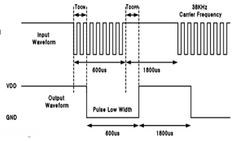
Infrared (IR) communication is a common, inexpensive, and easy to use wireless communication technology. IR light is undetectable to the human eye because it has a slightly longer wavelength (typically 950nm) than normal light (380-780nm) – perfect for wireless communication. An IR remote works by turning a LED on and off in a particular pattern. However, to prevent interference from IR sources such as sunlight or other lights, the LED is not turned on steadily, but is turned on and off at a modulation frequency (typically 36, 38, or 40kHz).

The time when a modulated signal is being sent is called a mark, and when the LED is off is called a space. Most used IR-remotes use a modulation frequency of 38kHz which means that a mark is represented by a fast (38.000 times/second) “on/off” switching of the IR LED.

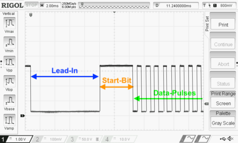
An IR-message starts with a lead-in pulse that is much longer than the other pulses. Then there is a start-bit, then comes the actual data and then again a long pulse, to indicate the end of the IR-message (not shown on the image).
Design considerations
- an IR-receiver-diode to capture the IR-messages
- an IR-transmitter (IR LED’s 950nm) to send IR-messages
- some processing power
- storage for saving the captured IR-messages
- two status LED’s
- the device needs to work with all Infrared remotes that modulate the Infrared signal at 38kHz
- it must be able to capture 400 pulse-long messages (I need to be able to capture from and send commands to my Airco/Heater).
The obvious choice to interface with the device is by using a webserver and restAPI and consequently the device needs an internet connection. The ESP8266 with its builtin WiFi and flash filesystem storage is the logical processor for this project.
Project setup
The best way to develop any project is by slicing it into small, logical parts and developing and testing these parts one at the time. For now I see three major parts:
- The IR-receiver circuit
- The IR-sender circuit
- The software to glue everything together
The development will be done with the 1of!-boards as they are cheap and easy to use. For the initial setup the 1of!-Wemos processor board is the board of choice as it is easily programmed with a USB cable and for the rest of the circuity a 1of!-Solderless bread board is used. If I’m satisfied with the circuit on the 1of!-Solderless board I will flash the firmware to a 1of!-ESP12 processor board and build the circuitry on a 1of!-Proto board.
The IR signal processing is handled by a fantastic library [v2.6.2 (20190616)] written by Ken Shirriff, David Conran and others. For additional details on how the library works, see Ken Shirriff’s blog: A Multi-Protocol Infrared remote Library for the Arduino.

 Follow
Hoi Willem!
Leuk project, ik zocht nog zo iets! Ik wil mijn airco automatiseren op basis van sensoren van de omgeving (daarnaast ook de aansturing van een luchtbevochtiger en de automatische radiatorknoppen) om zo het klimaat op mijn kantoor optimaal te houden. Ik ga er zeker naar kijken!
Gr, Roland