[ 17,380 keer bekeken / views ]
Developing hardware almost always run through the same stages:
- It starts with an idea
- You design a concept on paper or in your head
- Using a solder-less breadboard you connect parts to see that it works as you hoped it
would - Depending on the number of units you need, you either design a PCB or you copy the
breadboard schematic to an experiment board - Task fulfilled! You can sit back and relax.
If you, as I do, regularly design devices with ESP8266 processors you run into the same pitfall every time. The form factor of the ESP8266 (f.i. the ESP-12) is not specially breadboard friendly.
Bringing the ESP8266 to the Breadboard
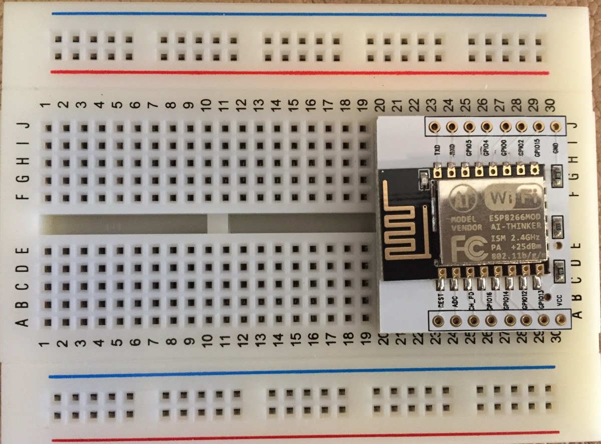
If you use a 400 holes breadboard (90x65mm) almost 33% of the available space is needed for an ‘ESP8266 on a piggy board’ and more alarming: There are no holes besides the piggy board to connect wires to!
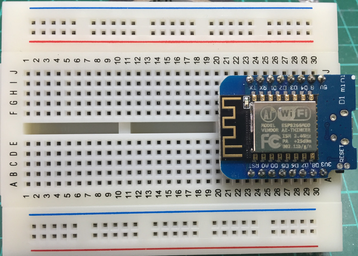
If you use a Wemos D1 you also lose about 30% of the available space, but at least you have the luxury of one row of holes on both sides of the Wemos D1.
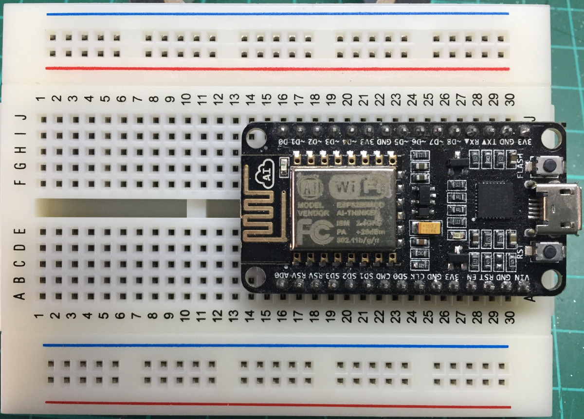
But if your favourite is the NodeMCU board the numbers are even larger.
You lose 60% of the solder-less bread board!
And why? If you want to design a device with an ESP8266 you always need a basic schematic just to operate the ESP8266. It is contra productive to set that up on a breadboard just because you want to interface a view passive or active components to make your idea work.

To sum it up, you need:
- five resistors
- two push buttons
- a voltage-regulator
- circuitry that delivers the 3v3 needed by the ESP8266
- a pin-header to upload firmware to the ESP8266.
A total of ten – eleven components that évery ESP8266 design needs.
And yes! there are benefits in using a Wemos D1 or NodeMCU board for the fact that they have all the hardware I described before ánd they have an USB to Serial chip on board. Because of that chip you can easily program these boards by just connecting the USB cable to your computer and press the upload icon on the Arduino IDE.
But…they are way to complex!
If you design a device with a ESP8266 you almost certainly do that because of the WiFi functionality of that processor. And once you have configured the WiFi settings you don’t need the USB to Serial chip anymore. Even updating the device with new firmware can easily be done “Over The Air”! So, if you want to develop a device with an ESP8266, the USB to Serial chip will make your design much more complex and more expensive, you need special skills or tools to solder the chip on a PCB and you will probably never use the functionality in real life devices.
And there are more arguments not to use these bulky boards for developing your own devices (apart from the fact that it is far more satisfying to design everything yourself). For instance if your device needs the ESP8266’s Analogue to Digital Convertor (ADC) and you start of with the Wemos D1 you need to know there is a voltage divider on the Wemos connected to the ADC pin and you have to make sure you use the same voltage divider in your overall design. And I get so confused by the naming of the IO-pins. You have the physical pin number (is pin 1 on the left top or ..), the made up ‘D-number’ and the underlying GPIO-number. Why?? And you can solder the pin-headers on the Wemos D1 with the ESP8266 on top or on the bottom. That messes up the physical pin numbering quit a lot!
Therefore I designed a solution that can be used as a development platform with a breadboard an experimenter board or an “one of a kind” end product.
Lets bring the Breadboard to the ESP8266
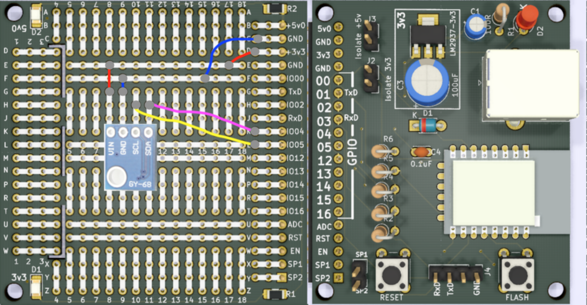
What I have done is made a processor board with an ESP8266, USB power, 3v3 regulator, a view resistors and elco’s, a Reset and Flash button and a 20 pole connector with all the available and usable pins from the ESP8266 plus GND, 3v3 and 5 volt power lines. You can choose to power the ESP8266 by soldering either a micro USB-B connector to the board or an ‘Arduino UNO’ large USB-B connector. To flash the ESP8266 you need an ‘USB to TTL’ cable or a simple USB-programmer and connect the ground, TxD and RxD to the programming header on the processor board (the 1of!-ESP12 can also be powered by the programming header if you apply 3v3 to the connector). To set the ESP8266 in flash-mode you press the flash-button and hold it pressed. Then you press the reset-button, release the reset-button and then release the flash- button. The ESP8266 is now in flash-mode and stay’s that way until you have uploaded your sketch or until you press the reset-button again (and if you program well, you can upload sketches wirelessly -‘Over The Air’- and never have to push buttons again).
The 20 pole connector has all the GPIO-pins 01, 02, 03, 04, 05, 12, 13, 14, 15 and 16 in that order so you never need to check what physical-pin is what ‘D-number’ is which GPIO-pin!
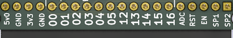
If you connect something to GPIO05 you program pinMode(5, mode) and digitalWrite(5, state) or digitalRead(5)!
SP1 and SP2 are not connected to anything but if you know what you’re doing and want to use GPIO09 and GPIO10 (which is not recommended) you can connect a wire from the ESP12 to these spare pins.
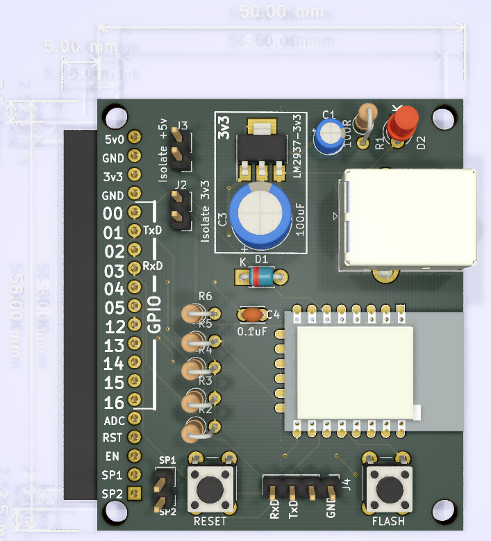
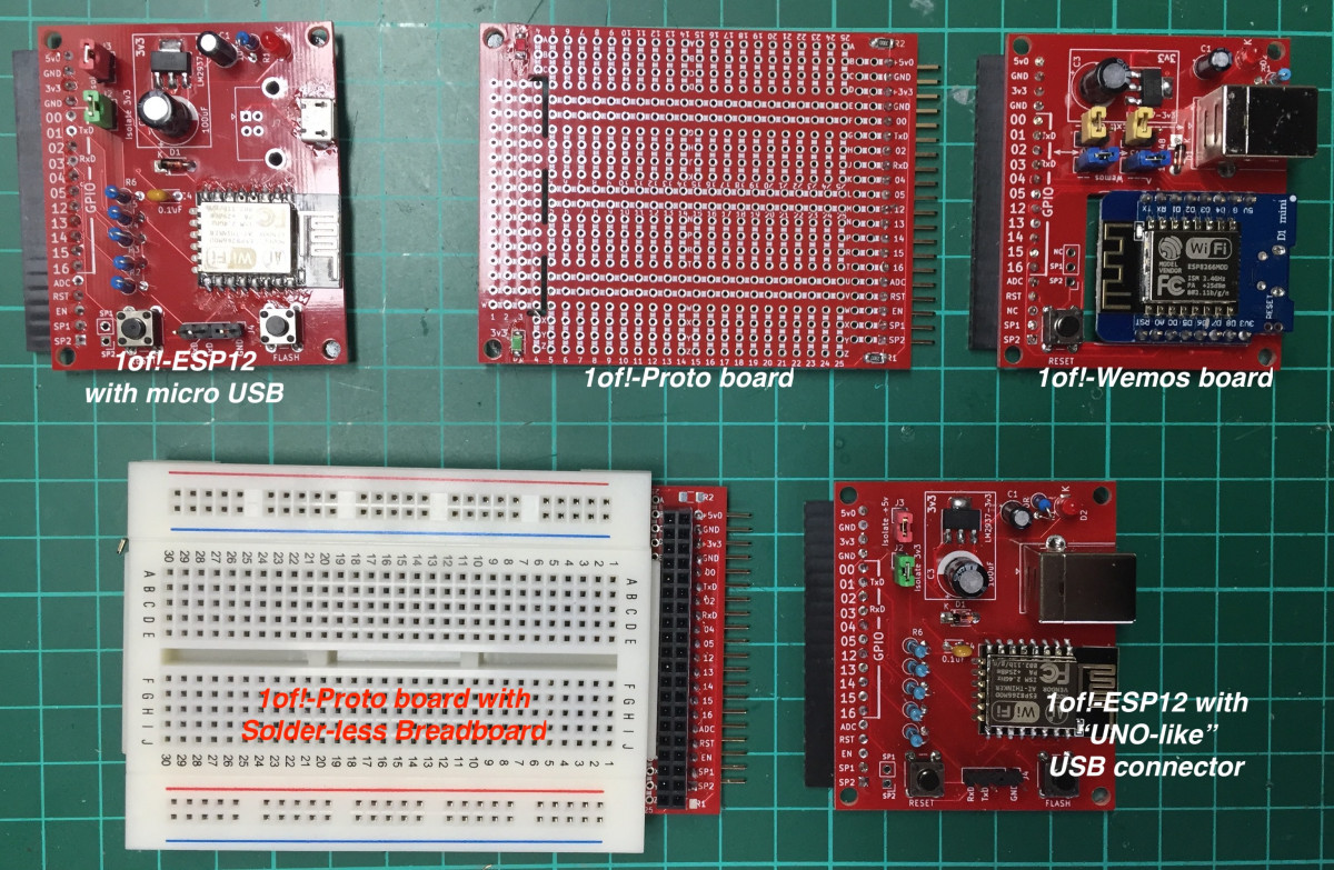
This board is called ‘1of!-ESP12’ and once you have one of these you can connect it with a ‘1of!-Proto’ board and start prototyping.
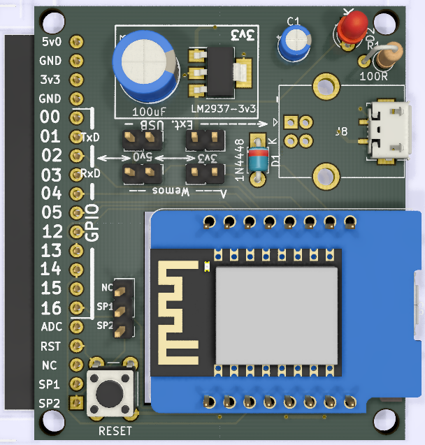
There is also a 1of!-Wemos board and there are two 1of!-Proto boards.
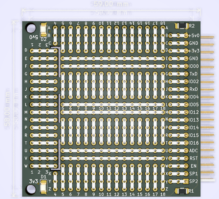
The smaller
Small 1of!-Proto board connected to the 1of!-ESP12 with the ‘UNO’-like USB-B connector
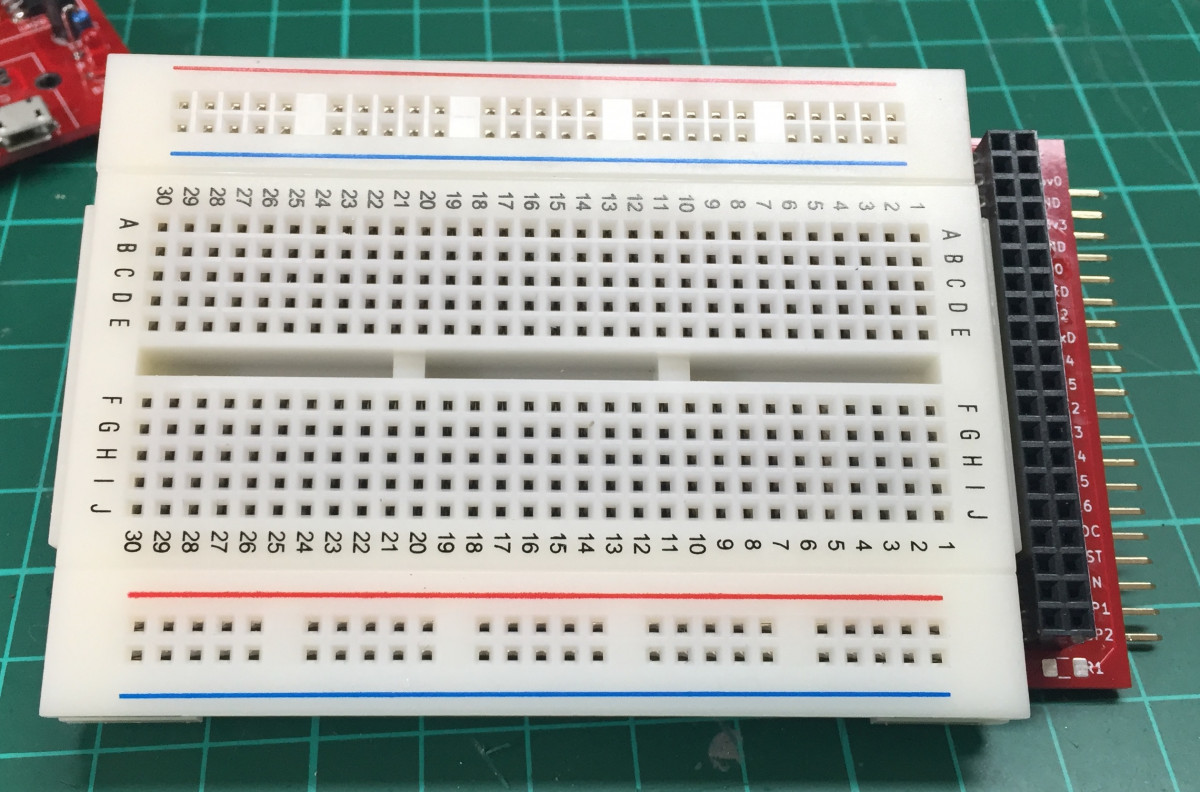
On the bigger board you can solder a 20 pin female-header and glue a 90 x 65mm solder-less breadboard on it.
If you made your device on the breadboard or on the experiment board you can simply disconnect it from the processor board and start your next project on a new 1of!-Proto board or you can make it an “one of a kind device” and put your design in a standard box. If you made a killer-device you can convert your proto design into a real PCB by simply combining your own design and the simple basic ESP8266 schematic into a complete schematic in your favorite CAD program and create the PCB from there.
 Follow
Make sure you use the right headers for the 1of!-proto boards!
Pingback: Universal InfraRed IoT Learning Remote | Willem's Website
Pingback: Slimme Meter Uitlezer versie 4Willem's Website