
15,792 keer bekeken / views
I will address two topics in this post.
The first one is about Rotary Encoders and what you can do with them. The second is about the Inter-Integrated Circuit protocol (I²C), developed by Philips.
Een in het Nederlands vertaalde versie van deze post kunt je hier vinden.
Rotary Encoders
A Rotary Encoder is a device that looks (physically) like a potentiometer but it does not vary the resistance between two/three connectors. Instead it gives pulses when the axle is rotated. Another difference with the potentiometer is that you can rotate the axle over 360° (in fact, there is no limit in how many degrees you can rotate the axle).
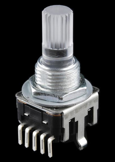
Most Rotary Encoders have a switch that is activated when you press the axle. And then there are Rotary Encoders that also have a three colour LED inside (RGB Rotary Encoder) which give you the option to feedback to the user a pallet of colours.
The Rotary Encoder generate pulses when the axle is rotated. Most Rotary Encoders generate 24 pulses at every 360° rotation. In your program you can count these pulses and let the program act on it (for instance: de- or in-crease the voltage of a bench power supply or step through a menu-list).
You may ask: “why use a Rotary Encoder and not just use a potentiometer?”. Well of course there is no “this is better than that” answer. It depends on the project at hand. If you build an analogue HiFi amplifier the potentiometer is probably the better choice. If you have a project with a microprocessor the (digital) Rotary Encoder gives you a lot of options to create a nice user interface (with maybe a fine/coarse change depending on the axle pushed short or long and a coloured feedback to show which mode is active).
This is an example Sketch to “read” a Rotary Encoder. You need hardware bounce control circuitry on pin A and B of the rotary Encoder to make it work reliably:
#define outputA 6
#define outputB 7

int rotVal = 0;
int rotState;
int rotLastState;

void setup() {
    pinMode (outputA,INPUT);
    pinMode (outputB,INPUT);
    Serial.begin (115200);
    // Reads the initial state of the outputA
    rotLastState = digitalRead(outputA);
} // setup()

void loop()
{
    rotState = digitalRead(outputA);
    // If the previous and the current state of
    // the outputA are different, that means a
    // Pulse has occured
    if (rotState != rotLastState){
      // If the outputB state is different to the outputA state,
      // the encoder is rotating clockwise
      if (digitalRead(outputB) != rotState) {
        rotVal ++;
      } else {
        rotVal --;
      }
      Serial.print(F("Position: "));
      Serial.println(rotVal);
    }
    rotLastState = rotState; // Update the previous state to
                             // the current state
}  // loop()
There is a drawback on using a Rotary Encoder in your project: You need a lot of pins!
One RGB Rotary Encoder needs two GPIO pins for the Encoder itself (plus GND), then you need one GPIO pin for the push switch and three GPIO pins for the RGB LED. Thats a total of six GPIO pins! On, for instance an ESP8266 that leaves only three free GPIO pins to control the rest of your project! On an Arduino UNO you have more free GPIO pins so one Rotary Encoder will not be a problem. But what if you want to connect two or even three Rotary Encoders. On an ESP8266 that’s impossible, but on an Arduino UNO you will also run out of free GPIO pins.
Luckily, there is a solution!
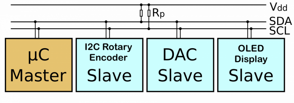
The Inter-Integrated Circuit bus (I²C)
This is called a (data) “bus” because you can connect a lot of devices at it. The “bus” exists of two lines. A clock line (SCL) and a data line (SDA). There is always (at least) one “master” device and all the other devices are “slave” devices. Every device has a unique address to differentiate between each other. I will not go into the depths of the I²C protocol, but normally the master will claim control over the bus and sends a request to a slave with a specific address. The slave in turn will take action on the request either by performing a specific action in the slave itself, by sending data back to the master or simply by sending an acknowledge back to the master to let him know he received the request. Here you can read more about the I²C protocol.
The I²C Rotary Encoder
Wouldn’t it be nice to connect a Rotary Encoder using only the two wires of the I²C bus!?
And that is what this post really is about: A Rotary Encoder that you connect via the I²C bus and control with the I²C protocol.
I developed the firmware and a small PCB with an ATtiny841 micro processor. I chose the ATtiny841 because it has Wire hardware (the layer underneath I²C) for a Slave builtin.
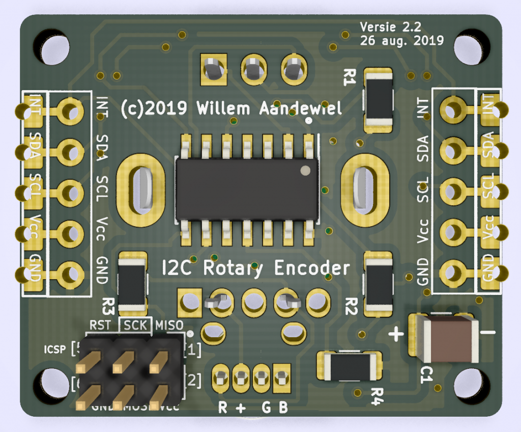
The firmware makes the ATtiny841 act like a ‘normal’ I²C Slave at one end and interface with a RGB Rotary Encoder at the other end. For ease of use I wrote an Arduino/ESP8266 Library to interface with the I²C RotaryEncoder.
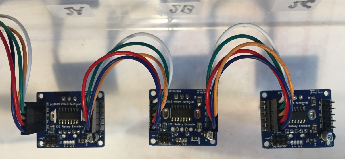
With this setup it is possible to connect as many (literally!) I²C RotaryEncoders to your microprocessor as you like and still only use two GPIO pins. You can even connect other I²C devices (display’s, sensors etc.) to the same two GPIO pins leaving a lot of GPIO pins free for other purposes.
If you want, you can use the Interrupt pin of the I²C RotaryEncoder.
This pin generates an interrupt for every change in the position of the rotary axle or push button. All I²C RotaryEncoders share the same Interrupt line.
Here you can buy this I2C Rotary Encoder.
How to use the I²C RotaryEncoder in your project
The below code is an example Sketch to interface with the I²C RotaryEncoder (using the Interrupt line):
/* Sketch to show the use of the I2C_RotaryEncoder */

#define I2C_DEFAULT_ADDRESS   0x28  // the 7-bit address

#include <i2c_rotaryencoder.h>

I2CRE     Encoder;     // Create instance of the I2CRE object

int16_t   rotVal;
volatile bool interruptPending = false;

//=======================================================
ISR_PREFIX void handleInterrupt()
{
  interruptPending = true;
}

//=======================================================
void handleRotaryEncoder()
{
  byte statusReg = Encoder.getStatus();
  if (statusReg == 0) return;

  if (Encoder.isRotValChanged() ) {
    Serial.print(F("Request Value of ROTARY .......... "));
    rotVal = Encoder.getRotVal();
    Serial.print(F("["));
    Serial.print(rotVal);
    Serial.println(F("]"));
  }

  if (Encoder.isButtonPressed() ) {
    Serial.println(F("-------> Button Pressed"));
  }
  if (Encoder.isButtonQuickReleased() ) {
    Serial.println(F("-------> Quick Release"));
    Encoder.setRotVal(0);            // or do something else
    Encoder.setRGBcolor(200, 0, 0);  // Red
  }
  if (Encoder.isButtonMidReleased() ) {
    Serial.println(F("-------> Mid Release"));
    Encoder.setRotVal(255);          // or do something else
    Encoder.setRGBcolor(0, 200, 0);  // Green
  }
  if (Encoder.isButtonLongReleased() ) {
    Serial.println(F("-------> Long Release"));
    Encoder.setRotVal(128);            // or do something else
     Encoder.setRGBcolor(0, 0, 200);   // Blue
  }

} // handleRotaryEncoder();

//=======================================================
void setup()
{
  Serial.begin(115200);
  Serial.println(F("Start I2C-Rotary-Encoder Basic ..."));
  Serial.print(F("Setup Wire .."));
  Wire.begin();
  Serial.println(F(".. done"));

  pinMode(_INTERRUPTPIN, INPUT_PULLUP);
  attachInterrupt(digitalPinToInterrupt(_INTERRUPTPIN)
                                        , handleInterrupt
                                        , FALLING);

  if (!Encoder.begin(Wire, I2C_DEFAULT_ADDRESS)) {
     Serial.println(F(".. Error connecting to I2C slave .."));
     delay(1000);
     return; // restart the micro processor
 }

  Encoder.setLedGreen(128); // turn green led on half intensity

  interruptPending  = false;

  Serial.println(F("setup() done .. \n"));

} // setup()


//============================================================
void loop()
{
  if (interruptPending) {
     interruptPending = false;
     handleRotaryEncoder();
  } // handle interrupt ..

  //
  // do other stuff ..
  //

} // loop() </i2c_rotaryencoder.h>
I2C Rotary Library
The I²C_RotaryLibrary has the following methods:
The library gives you the following setters:
|
Setter |
Returns |
Parms |
Description |
|
setRotVal() |
bool |
int16_t |
set the value of the Rotary Encoder (-5000 .. + 5000) |
|
setRotStep() |
bool |
int16_t |
set the rotary Step (1 .. 50) |
|
setRotMin() |
bool |
int16_t |
set the Minimum rotary value (-5000 .. +5000) |
|
setRotMax() |
bool |
int16_t |
set the Maximum rotary value (-5000 .. +5000) |
|
setRotSpinTime() |
bool |
uint8_t |
set the Rotary Spin thime value (2 .. 100 milli seconds) |
|
setRGBcolor() |
bool |
uint8_t, uint8_t, uint8_t |
set the color of all 3 leds Red, Green, Blue (0 .. 255, 0 .. 255, 0 .. 255) |
|
setRGBcolor() |
bool |
uint32_t |
set the RGB color of all 3 leds (0x000000 .. 0xFFFFFF) |
|
setLedRed() |
bool |
uint8_t |
set the PWM value of the Red led (0 .. 255) |
|
setLedGreen() |
bool |
uint8_t |
set the PWM value of the Green led (0 .. 255) |
|
setLedBlue() |
bool |
uint8_t |
set the PWM value of the Blue led (0 .. 255) |
|
setDebounceTime() |
bool |
uint8_t |
set the Debounce Time of the switch (5 .. 250 micro seconds) |
|
setMidPressTime() |
bool |
uint16_t |
set the Mid Press Time of the switch (100 .. 5000 milli seconds) |
|
setLongPressTime() |
bool |
uint16_t |
set the Long Press Time of the switch (300 .. 10000 milli seconds) |
|
setModeSetBit() |
bool |
uint8_t |
set the Mode Bit (STNG_HWROTDIR | STNG_FLIPMODE | STNG_TURNMODE) |
|
setModeClearBit() |
bool |
uint8_t |
clears the Mode Bit (STNG_HWROTDIR | STNG_FLIPMODE | STNG_TURNMODE) |
|
setI²Caddress() |
bool |
uint8_t |
set a new I²C address for this Slave (1 .. 127) |
|
writeCommand() |
bool |
uint8_t |
write a command to the Slave (CMD_READCONF | CMD_WRITECONF | CMD_REBOOT) |
The library gives you the following getters:
|
Getter |
Returns |
Parms |
Description |
|
getStatus() |
uint8_t |
none |
reads the status byte |
|
getRotVal() |
int16_t |
none |
read the value of the rotary (-5000 .. +5000) |
|
getRotStep() |
int16_t |
none |
read the rotary Step (1 .. 50) |
|
getRotMin() |
int16_t |
none |
read the minimum rotary value (-5000 .. +5000) |
|
getRotMax() |
int16_t |
none |
read the maximum rotary value (-5000 .. +5000) |
|
getRotSpinTime() |
uint8_t |
none |
read the rotary spin time (2 .. 100 milli seconds) |
|
getWhoAmI() |
int8_t |
none |
read the Address Register |
|
getLedRed() |
uint8_t |
none |
read the current Red led PWM value (0 .. 255) |
|
getLedGreen() |
uint8_t |
none |
read the current Green led PWM value (0 .. 255) |
|
getLedBlue() |
uint8_t |
none |
read the current Blue led PWM value (0 .. 255) |
|
getDebounceTime() |
uint8_t |
none |
read the Debounce Time of the switch (5 .. 250 micro seconds) |
|
getMidPressTime() |
uint16_t |
none |
read the Mid Press Time of the switch (100 .. 5000 milli seconds) |
|
getLongPressTime() |
uint16_t |
none |
read the Long Press Time of the switch (300 .. 10000 milli seconds) |
|
getMajorRelease() |
uint8_t |
none |
read the Major Firmware Release byte (0 .. 255) |
|
getMinorRelease() |
uint8_t |
none |
read the Minor Firmware Release byte (0 .. 255) |
|
getModeSettings() |
uint8_t |
none |
read the Mode register byte (0 .. 255) |
|
getModeSettings() |
bool |
uint8_t |
read the Mode register byte and test against (STNG_HWROTDIR | STNG_FLIPMODE | STNG_TURNMODE) |
And the library gives you the following helpers:
|
Helper |
Returns |
Parms |
Description |
|
isRotValChanged() |
bool |
none |
true if the Rotary Value has changed |
|
isRotValChangedUp() |
bool |
none |
true if the Rotary Value > previous value |
|
isRotValChangedDown() |
bool |
none |
true if the Rotary Value < previous value |
|
isButtonPressed() |
bool |
none |
true if the Button is pressed |
|
isButtonQuickReleased() |
bool |
none |
true if the Button is released before midPressTime |
|
isButtonMidReleased() |
bool |
none |
true if the Button is released between midPressTime and longPressTime |
|
isButtonLongReleased() |
bool |
none |
true if the Button is released after longPressTime |
 Follow
Hallo Willem,
ik wil wel een paar printjes van die Rotary Encoder kopen.
Heb jij nog een paar?
Want het lijkt mij heelerg interessant voor een paar Solar Projecten ivm Victron.
Met vriendelijke Groten,
Mike
Hi Mike,
Ik ben vandaag niet in mijn Work Shop.
Morgen zal ik kijken of ik nog wat PCB’s heb en dan stuur ik je een PM.
Dankje welvoor het na kijken.
Hallo Willem,
Werk je nog aan dit project? Op open circuit kon ik het product niet meer vinden.
Martin,
Het project is wat mij betreft “af”.
Opencircuit heeft het project nooit echt in zijn webshop opgenomen omdat er niet genoeg animo voor is.
Als je interesse hebt heb ik nog wel een paar printjes á €5 excl. portokosten.
Willem,
Voor testen is dat zeker een optie, uiteindelijk willen we de oplossing implementeren in een van onze projecten. The ATTiny is het hart van de oplossing.
als de dev-bordjes goed werken zouden we dit willen integreren in onze hardware. Sta je open om de oplossing te integreren aangezien we de binaries en schema nodig hebben.
Stuur me anders een persoonlijk bericht, aangezien dit wellicht niet iets is om via het forum te bespreken.
Entered the wrong eMail address
Ok, I will remove the wrong eMail address from the system
Hi,
Great project!
Can I buy a kid of this rotary encoder somewhere?
Opencircuit sells them “ready to use”