[ 13,002 keer bekeken / views ]
A friend of my keeps bees as a hobby. I’m not fond of flying, stinging insects, but because he was so enthusiastic my partner and I went to visit an apiary in the ‘Corversbos’ in Hilversum and it was nice.
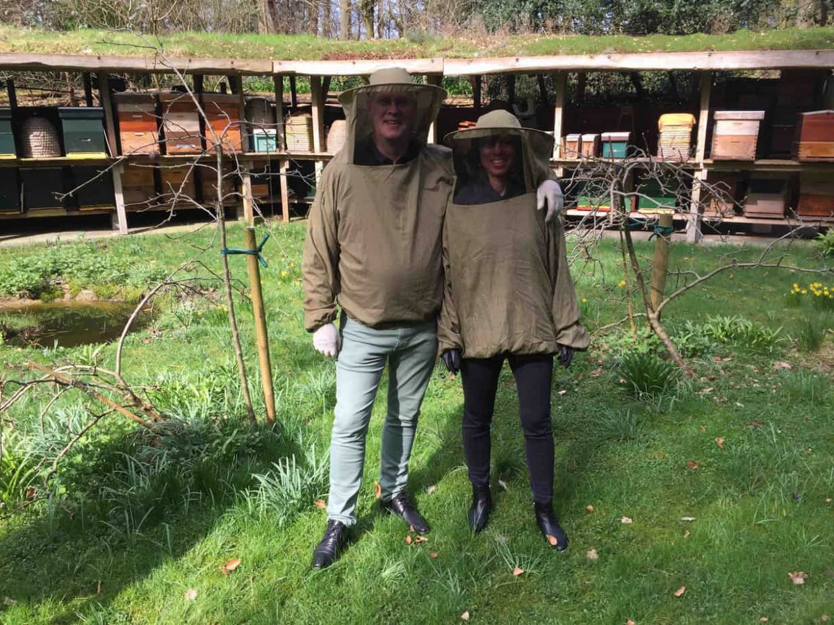
The bees (contrary to wasps) are relaxed, friendly creatures that do no harm – as long as you comply to certain rules (e.g.: don’t stand in their flight path to the landing zone of the beehive!). I think, if they behave them selfs, I like those little creatures.
One of the reasons to visit the apiary was to have a look at some beehives as my friend want’s to log temperature data during the year to monitor the health of the beehive.
And that’s what this blog is about.
The objective is to create a device that will measure the temperature inside the beehive at certain intervals, for instance every one, two, three, four or six hours.
Design goals
The logging unit (from now on the “BeeHave Logger”) has to operate in a -more or less- harsh environment (the bee’s will stuff every hole with wax). The unit has to operate without intervention for at least one month on batteries, but preferable for two or three months. The BeeHave Logger has to be waterproof. The temperature sensor must be placed inside the honeycomb.
Must haves
The BeeHave Logger obviously needs some sort of temperature measuring device. The DS18B20 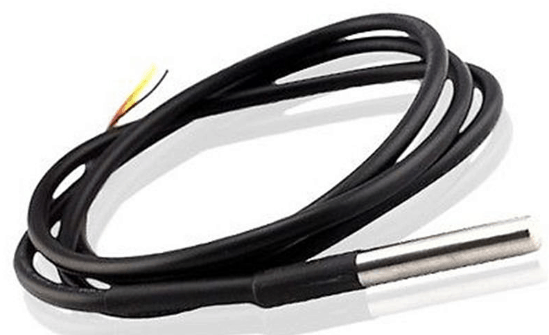 seems made for this project. It operates on a One Wire bus, is completely encapsulated and has a connecting cable of about one meter.
To have an accurate timing device we need a Real Time Clock. On eBay I found the DS3231 module that not only keeps accurate track of time, but it can also measure the temperature (it uses the temperature to correct the crystal frequency).  Together with the DS18B20 we can now measure the temperature inside the beehive, but also the temperature outside the beehive (actually, the BeeHave Logger will be placed between the inner and outer top covers, so the “outside temperature” is in fact, only more or less “outside”).
We need a medium to log the data to. First idea was to use a (micro) SD card.
As the BeeHave Logger is battery operated it would be nice to log the battery voltage as well (the battery voltage is a fair indication of the available energy left in the battery).
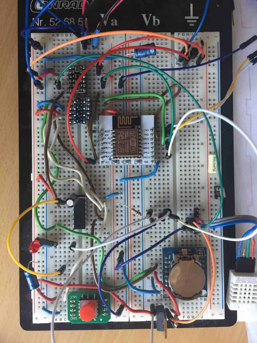
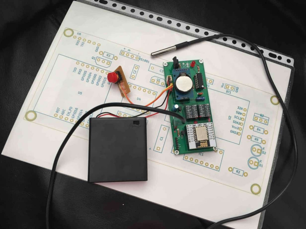
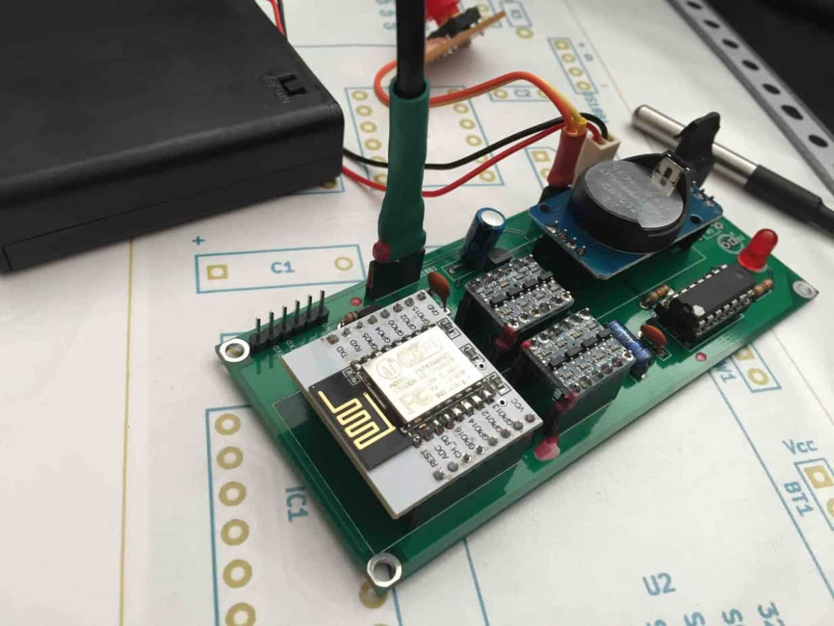
Putting it together
I was recently pointed to the ESP8266 processor family. These are very capable devices with a lot of processing power and memory. And they are cheap! The ESP12 seems very suited for the job. The only drawback is the Vcc of the ESP12 is only 3v3 while most modules work at 5 volt (“Arduino compatible”). To connect these devices to each other we need level-shifters.
To prolong battery life the devices should sleep between measurements.  But as the microSD card module, the DS3231 module and the DS18B20 have no “sleep mode”, we have to disconnect them from the battery if the ESP12 is asleep. For this we will use a (p-channel) MosFet transistor to switch the power to these modules.
The 3v3 power for the ESP12 will be derived from the battery with a voltage regulator (LDO).
Design choices
For this setup we need one GPIO pin for controlling the MosFet switch. One for reading the DS18B20 (One Wire bus), two for the DS3231 (I2C bus) and four for the microSD card (SPI bus). A total of eight GPIO pins. Although the ESP12 has nine GPIO pins, only eight are available to us, as GPIO16 is the “wake up” pin of the processor (this pin goes high after the timeout has occurred and must be connected to the “Reset” pin to wake the ESP12 from deep sleep ..
The ESP12 also has a pin (ADC) to measure analogue values (as the battery voltage) but it will only do this in the 0-1 volt range. Therefore a voltage divider is needed to bring back the 4.8 volt of the four rechargeable cells to a 1 volt range. I’m not very fond of voltage dividers.
For the BeeHave Logger to be waterproof a SD card is not ideal. You need an opening in the casing to insert and remove the card and, if it is a microSD card, all will be very tiny which will make a waterproof casing difficult to fabricate. To overcome this problem we introduce a second device that can make contact with the BeeHave Logger and read the data from the loggers SD card. We shall name this device the ‘BeeHave Reader’. The BeeHave Logger and Reader will have to communicate with each other so the data captured by the BeeHave Logger can be transferred to the BeeHave Reader and stored in csv format on a SD card in the Reader.
The SD card from the Reader can then be placed in a computer at home to analyse the logged data. In this setup the BeeHave Reader does not have to be waterproof and of course you only need one BeeHave Reader to read data from a lot of BeeHave Loggers!
Various options were tested for the communication between the BeeHave Logger and the BeeHave Reader. 433 MHz RF transceivers, bluetooth transceivers and WiFi. The reason not to just go for the WiFi option in the first place (as the ESP8266 has WiFi built in) was the fact that WiFi is quite power hungry (200-300mAh). But it turned out to be the most reliable way to communicate between the Logger (as WiFi client) and the Reader (as WiFi Access Point). But then an other problem presented itself. The BeeHave Logger is in deep sleep most of the time. Every now and then it wakes up, does some logging and goes to sleep again. But if we want to collect data from the Logger to the Reader we need a second way to wake up the Logger. This can be done by a simple (reed) switch. I can connect the switch and GPIO16 together (with some passive components) to the Reset pin, but then there is no way to tell why the ESP12 woke up.
To establish communication with the Reader, the Logger has to scan WiFi for a specific AP. This can take up to twenty seconds and all that time the Logger uses a lot of power. Then, if it does not find the AP it probably was not woken up by the Wakeup button and just has to do some measurement, write it to the SD card and go back to deep sleep again. From a power consumption point of view, we don’t want the Logger to startup WiFi every time it wakes up but only when the Wakeup Button was pushed and the Reader is in the near vicinity.
As said before, there is only one way to wake up the ESP from deep sleep and that’s by switching the “Reset” pin high for a short period of time. We know we can connect GPIO16 and a button to the Reset pin (with some passive components) but then there is still no way to figure out whether the pin was switched because of a timeout event or because the Wakeup button was pressed.
To overcome these problems we will introduce a second processor (ATTiny84). The ATTiny84 can also be put to deep sleep, but is can be woken by all GPIO pins. So we connect the GPIO16 pin of the ESP to PCINT1 (PA1) of the ATTiny84. The Wakeup button (or reed switch) will be connected to the PCINT0 (PA0) pin of the ATTiny84. The ATTiny84 will be programmed as an I2C device and depending on the type of wakeup event it will write a value to a “register”. It then will switch PA2 high for a short time and that will trigger the ESP Reset pin. Both processors are awake now. First thing the ESP does is read the specific register on the ATTiny84 via the I2C bus and, by the value it reads, now knows it was woken by it’s own internal timer or by someone pressing the Wakeup button. One other nice future of this setup is that we can let the ATTiny84 read his Vcc (which is the battery voltage). The ATTiny84 will store this also in a specific register and the ESP can also read this register (the battery voltage) via the I2C bus.
Then someone pointed me to a library for the ESP8266 that will deploy the internal EEPROM of the ESP as a file system (FS.h). The ESP12 has 4MB EEPROM memory, more than enough to log a few months of data. So, the (micro)SD card is replaced by this internal “SD”-memory! One device less!
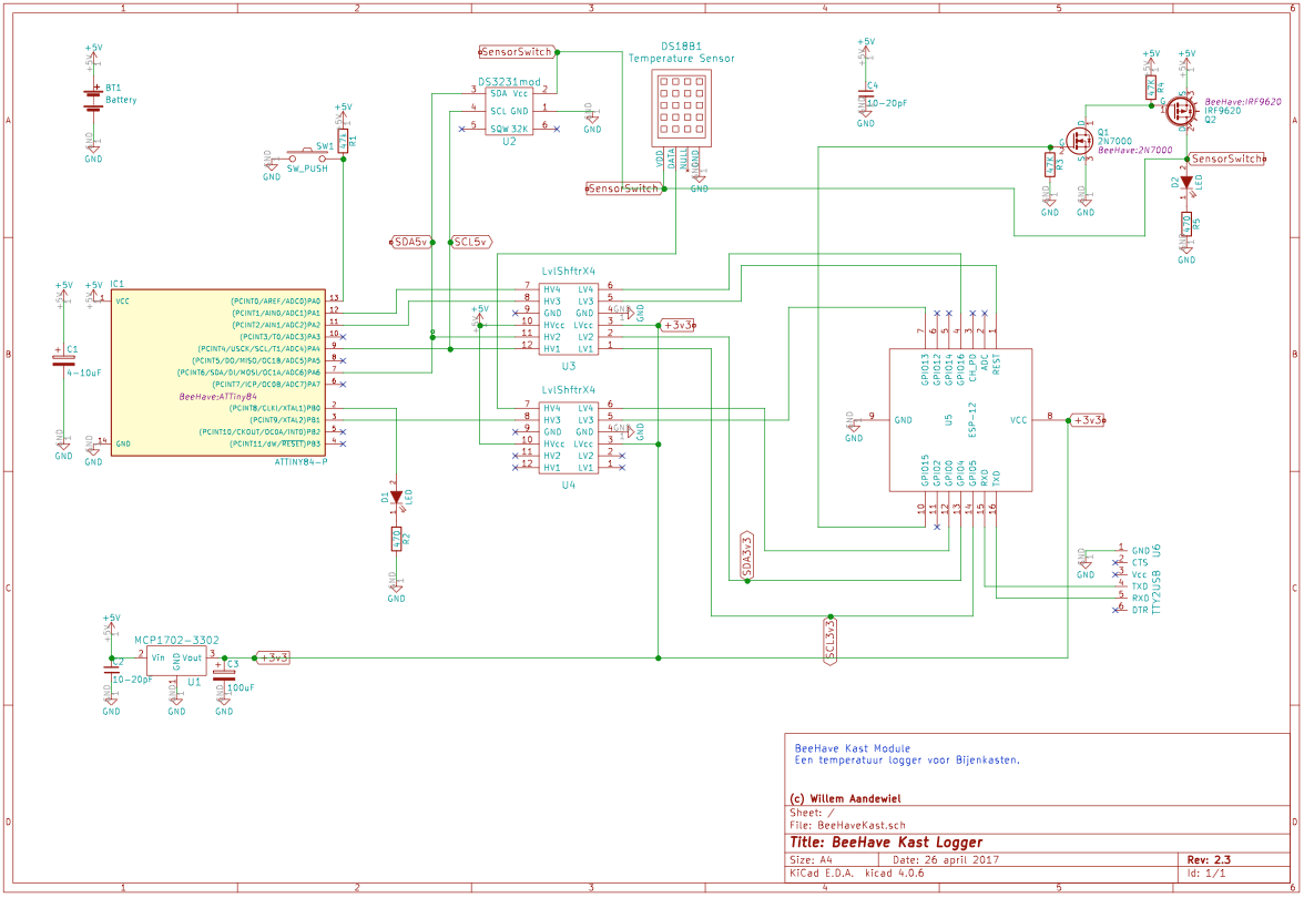
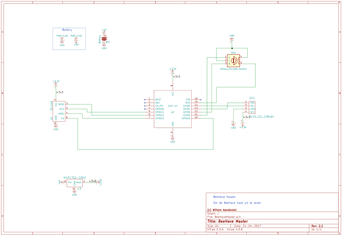
Schematic
The schematic is drawn with KiCAD. This really is great software. The only drawback is that I work on Mac’s and the implementation of KiCAD for the Mac has some quirks with the Magic Mouse (but they are working on it). It drives me mad that it zooms in and out without an apparent reason. But still, what you can do with this software is impressive (after connecting a second, “normal” optical mouse the erratic zooming in and out behaviar is gone).
As you can see, the MosFet switch is made out of two MosFet transistors. The n-channel MosFet switches the gate of the p-channel MosFet between +5 volt and GND. It is a very handy way to power the high-side of the modules.
Schematic BeeHave Logger
Schematic BeeHave Reader
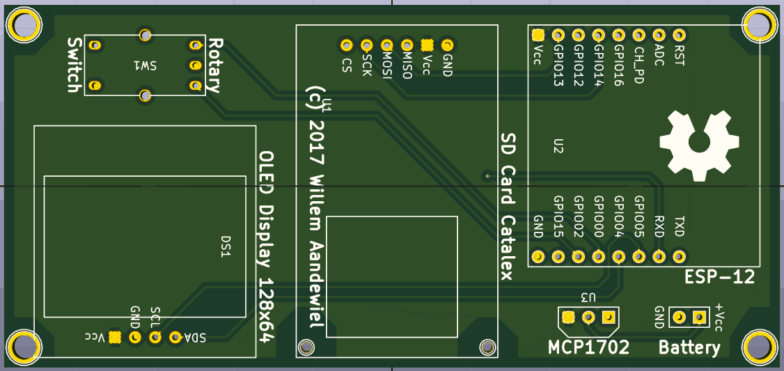
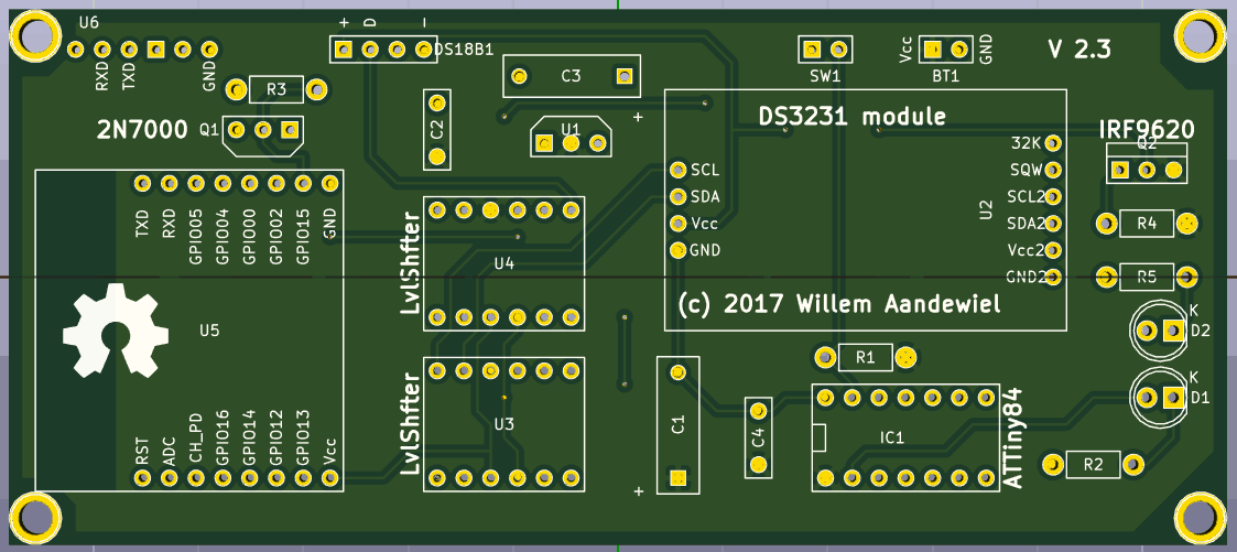
The software is “work in progress” but can be found on GitHub as are the Gerben Files to make the PCB. After creating the Gerben- and Drill-files I send them to PCBway. For $22,- they made me 10 pieces (there is an additional $25,- for transport). The time from sending the files to receiving the PCB’s was less than one week!! Impressive.
 Follow
Hoi Willem, dat is een heel leuk project en dat heb je ook heel goed beschreven. Het ziet er zeer professioneel uit en het zal me niet verrassen dat je bijdrage veel mensen motivatie geeft om ook eens iets leuks en praktisch te gaan bouwen. In het geval van de BeeHave ben ik er ook zeker dat Rob z’n bijen het wel fijn vinden dat er op hun temperatuur zo nauwkeurig opgepast word.
Ga zo door, voormalig klasgenoot! Groetjes, Han.
Hallo Han,
Long time no see! Er is een hoop gebeurd sinds we bij jouw vader weerstandjes en transistortjes kochten!
Wow Willem, hier worden bijen blij van. Nooit meer koude voetjes en vleugeltjes tijdens barre winters bijvoorbeeld omdat de imker in kan grijpen als het te koud wordt in de kast. Ze zullen je eeuwig – voor een bij is dat ‘s zomers 5 weken en in de winter zo’n 4 maanden – dankbaar zijn en nooit meer met hun angel vooruit gestoken op je af vliegen. Chapeau.
Dat heb je weer top gemaakt schat!!
Ga zo door 😘