
Example Programs
The I2C_RelaysMux library comes with two example programs. The first one is for an Arduino UNO board, the second, more elaborate example, is for an ESP8266 board.
I2C UNO RelaysMux Test
The I2C_UNO_RelaysMux_Test is for an Arduino UNO board.
After initialization (the setup() function) it loops over a readCommand(); function.
This function reads command from the Serial Monitor and, if the command is recognized, it will execute it. The following commands are valid:
| n=1; | set relay n to ‘closed’ (activate) [n= 1 to 16] |
| n=0; | set relay n to ‘open’ (de-activate) |
| all=1; | set all relays to ‘closed’ |
| all=0; | set all relays to ‘open’ |
| address48; | set I2C address to 0x48 (default) |
| address24; | set I2C address to 0x24 |
| board8; | set board type to 8-relays board |
| board16; | set board type to 16-relays board (default) |
| status; | I2C Relay Multiplexer status |
| pinstate; | List the state of all the relays |
| looptest; | Chasing relays until a new commend is entered |
| muxtest; | test on relays board (this test is performed local on the I2C Relay Multiplexer Board) |
| whoami; | returns I2C address of the I2C Relay Multiplexer Board |
| writeconfig; | write config to EEPROM (I2C address and board-type) |
| reboot; | reboot the I2C Relay Multiplexer Board |
| rescan; | re-scan for I2C Relay Multiplexer Board address |
| help; | Shows valid commands |
You can enter multiple commands at one line, separating them by a semicolon (;).
After a period of in-activity the looptest will automatically start.
I2C ESP8266 RelaysMux Test
The I2C_ESP8266_RelaysMux_Test is for an ESP8266 board. The functionality of this test program is the same as that of the I2C_UNO_RelaysMux_Test program with some added functionality.
For this program to work you have to add the credentials of your WiFi network (lines 61 and 62).
  #ifndef STASSID
  #define STASSID "your-ssid"
  #define STAPSK  "your-password"
  #endif
telnet
You can connect to the ESP8266 by the telnet protocol. This gives you the ability to remotely control the Relays Board! The commands are the same as from the Serial Console. A typical telnet session could look like this:
telnet 192.168.2.16     								<<< User input
Trying 192.168.2.16...
Connected to 192.168.2.16.
Escape character is '^]'.
command[]
help 																	<<< User input
command[help]

  Commands are:
    n=1;         -> sets relay n to 'closed'
    n=0;         -> sets relay n to 'open'
    all=1;       -> sets all relay's to 'closed'
    all=0;       -> sets all relay's to 'open'
    address48;   -> sets I2C address to 0x48
    address24;   -> sets I2C address to 0x24
    board8;      -> set's board to 8 relay's
    board16;     -> set's board to 16 relay's
    status;      -> I2C mux status
    pinstate;    -> List's state of all relay's
    looptest;    -> Chasing Relays test
    muxtest;     -> On board test
    whoami;      -> shows I2C address Slave MUX
    writeconfig; -> write config to eeprom
    reboot;      -> reboot I2C Mux
  * reScan;      -> re-scan I2C devices
    help;        -> shows all commands

pinstate															<<< User input
command[pinstate]
  Pin: 6543210987654321
State: LLLLLLLLLLLLLLLL

1=1;3=1;5=1;6=1;8=1;13=1;pinstate;				<<< User input
command[1=1]
command[3=1]
command[5=1]
command[6=1]
command[8=1]
command[13=1]
command[pinstate]
  Pin: 6543210987654321
State: LLLHLLLLHLHHLHLH

whoami											<<< User input
command[whoami]
>>> I am 0x48             *-- response from I2C Relay Multiplexer

address24										<<< User input
command[address24]
		*-- I2C Relay Multiplexer board reboots
		*-- with the new I2C address
		*-- The test software will rescan to find
		*-- this new address

pinstate											<<< User input
command[pinstate]
  Pin: 6543210987654321
State: LLLLLLLLLLLLLLLL
whoami													<<< User input
command[whoami]
>>> I am 0x24

board8													<<< User input
command[board8]

pinstate												<<< User input
command[pinstate]
  Pin: 87654321
State: LLLLLLLL

all=1;pinstate									<<< User input
command[all=1]
command[pinstate]
  Pin: 87654321
State: HHHHHHHH

all=0;pinstate									<<< User input
command[all=0]
command[pinstate]
  Pin: 87654321
State: LLLLLLLL
^]           					<<< User enters [Ctrl]+]
telnet> q							<<< User enters “q”
Connection closed.
Webserver
This test program also has a webserver to which you can connect to with a web-browser.
In your browser type the following URL:
http://testMux.local/
or
http://[ip-address-esp8266]/
The program presents a webpage like this:
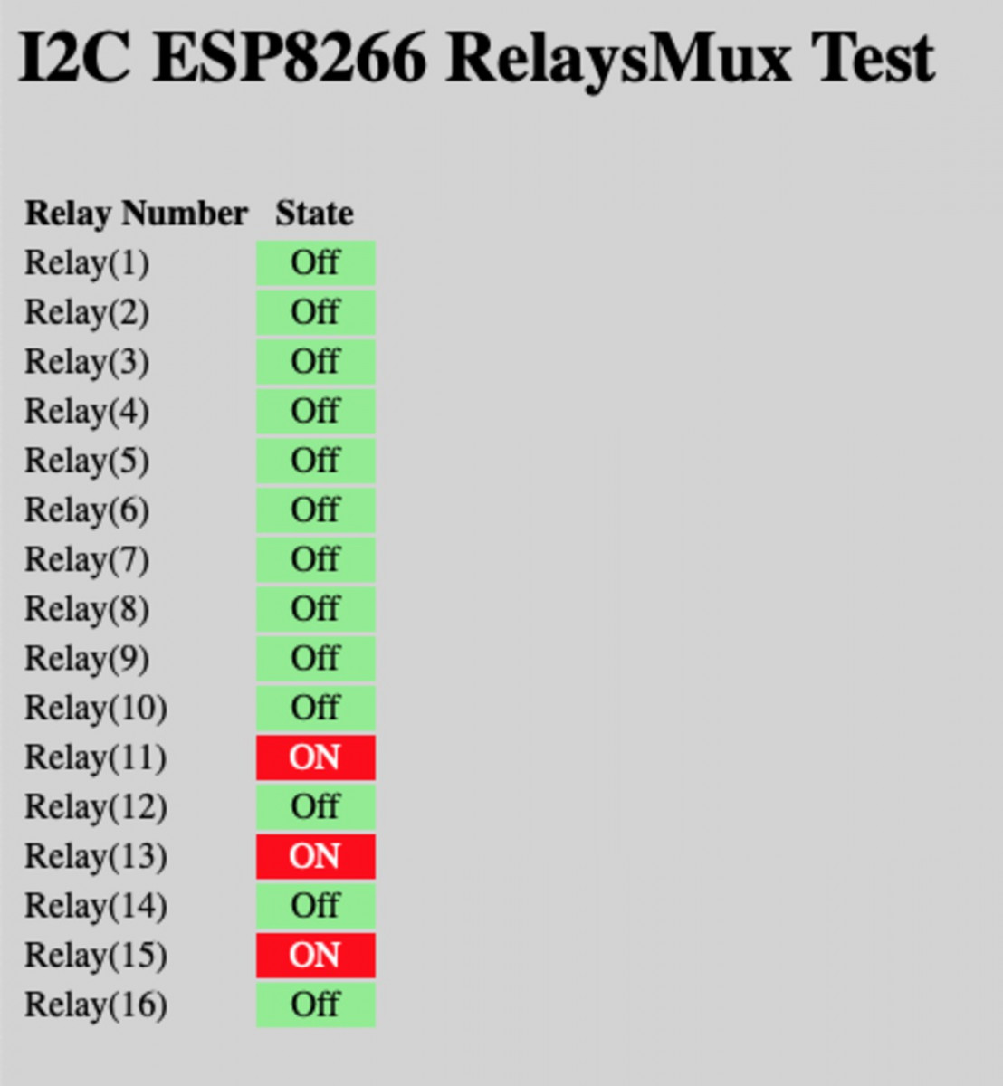
By clicking on the green “Off” or the red “ON” button you can activate or de-activate the corresponding relay (on a 8 relays board you will only see 8 buttons).
The refresh rate of the page is about 2 seconds, so it will lag a bit from the actual relay state.
I2C ATmega RelaysMux
This is the firmware for the ATmega328P-PU micro processor.
The principle of this firmware is quite simple. After setting all the GPIO pins as OUTPUT and HIGH (remember, the relay board uses HIGH input to de-activate the relays and a LOW input to activate a relay) it will read the configuration from EEPROM to determine the type of board (8 or 16 relays) and the I2C address to listen to.
Then it initializes the I2C bus with the correct I2C address and two callback functions
 Wire.onReceive(receiveEvent);
 Wire.onRequest(requestEvent);
If the I2C Master sends a byte of data to the I2C Slave the onRequest() event is triggered and that will call the receiveEvent() function. This function will then handle the incoming data. If the I2C Master wants to know what is inside a register it will first send the register number it want to know the value of and then it waits for the I2C Slave to send the requested data (handled in the requestEvent() function).
The I2C firmware is event-driven so there is no processing in the loop() function except for resetting the Watch Dog Timer.
To program the ATmega328P you can place it in a Arduino UNO board and program it the way you would normally program an Arduino UNO.
But for the firmware to work we first need to set some fuses of the ATmega328P before you can flash the firmware. It is absolutely necessary to do this or the firmware will not work!
You can set the fuses with avrdude (part of the Arduino IDE) with the following flags:
[...]/bin/avrdude -P usb -c usbtiny -b 9600 -B 100 -p ATmega328P
            -U lfuse:w:0xff:m -U hfuse:w:0xd6:m -U efuse:w:0xff:m
everything needs to be in one line!
 "[...]" is the path that the Arduino IDE uses to program the Arduino
Boards with an Atmel processor.
The “-P usb” and ”-c usbtiny” flags may be different if you don’t use an USB programmer.
For makers interested I do have some PCB’s to sell. I can even make a kit with all the parts, including a programmed ATmega328
 Follow
I am the lucky user of one of the first prototypes of this board as I had to control 9 valves of my underground floor heating systems. The hardware and software work like a charm and keep my house comfortably warm 🙂 Together with a whole lot of other hard- and software we developed but more about that later!