
15,896 keer bekeken / views
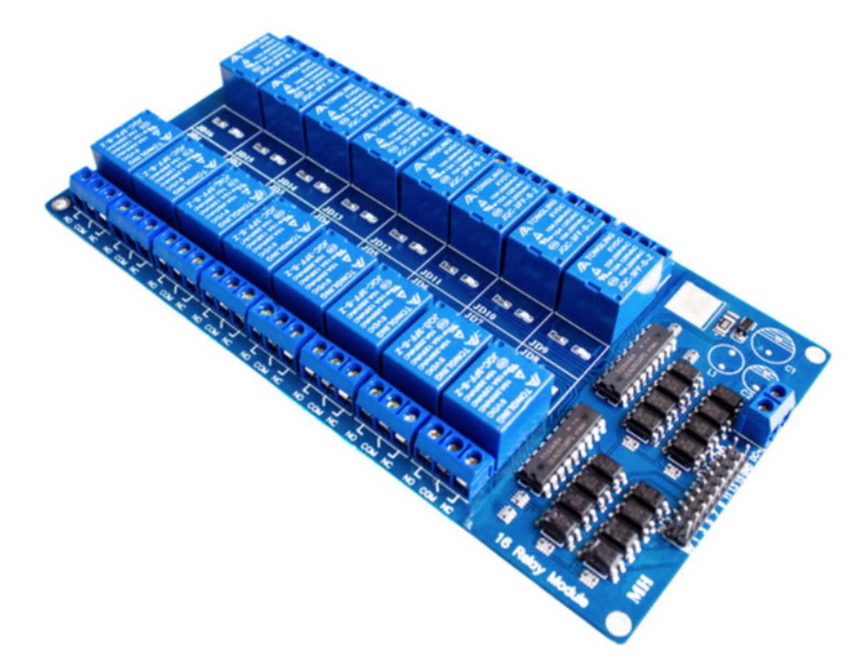
I recently worked on a project that needed to control a lot of relays. There are these nice boards with 8 or 16 relays that are well suited for my purpose. Both boards have a male pin header with GND and 5Volt pins on the outside and a pin for every relays (the 8 relays board uses a single row of ten pins, the 16 relays board uses two rows of ten pins). The logic is low for closing (activate) a relay and high for opening a relay.

The only problem is that for controlling so many relays with a micro processor you need a lot of wires and a micro processor with a lot of GPIO pins.
For this project the ESP8266 is the micro processor of choice due to it ability to connect to a local WiFi network, the speed and the amount of flash memory.
The only drawback is: The ESP8266 does not have enough GPIO pins for the task ahead.
The solution, of-course, is to interface with the relays board over I2C which only need two GPIO pins plus GND and Vlogic. But then we need a way to drive the relays board with I2C which, natively, it can’t!
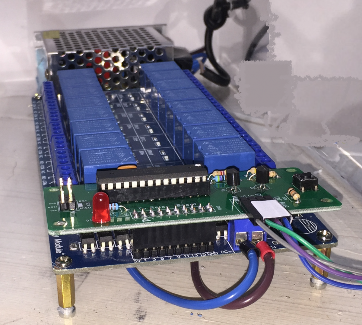
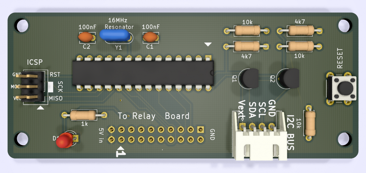
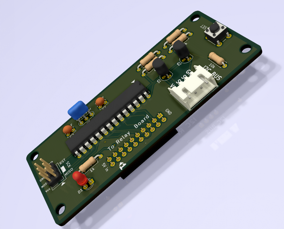
Therefor I designed a dedicated I2C multiplexer board to connect as a piggyback to these relays boards to make them I2C compliant!
Design Goals
The board should fit on both 8 and 16 relays boards with as little hassle as possible. The I2C bus must comply to both 3v3 and 5 volt logic so it can be used with, for instance, an Arduino UNO (5 volt) and modern 3v3 boards like the ESP family. For convenience it must be possible to program the ATmega328 by a standard ISP connector.
Opening and closing of a specific relay should be as easy as digitalWrite() to GPIO pins (we need an accompanying library for this).
How did I do it?
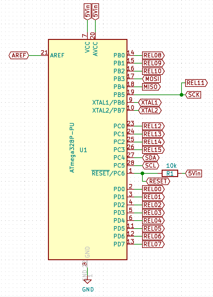
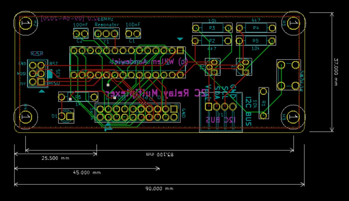
Well, I designed a board with an ATmega328P-PU micro processor which has 28 pins. Two of these pins are for Vcc (7 and 20) two for GND (8 and 22) two for the external oscillator (9 and 10) AREF (21) is connected to GND by a 100nF cap and RESET (1) is connected to a Reset circuit. That leaves us with 20 free pins. To be able to program the ATmega with an ISP we need three more pins: MOSI(17), MISO(18) and SCK(19) and of-course the I2C lines SDA(27) and SCL(28). But that’s 13 used pins out of 28 which leaves us with only 15 free pins! One pin short if we want a single pin for every single relay!!
Luckily, SCK is only used for programming when the Multiplexer is not connected to the relay board (to program the ATmega328 you must remove the I2C Relay Multiplexer Board from the Relay Board!). This means that pin 19 can be used for both SCK and for controlling a relay. Great!
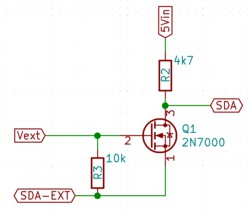
To be able to use the 5Volt I2C logic of the ATmega with the 3v3 I2C logic of modern boards we need two so called “Bi Directional Logic Level Shifters”. As the name implies, these devices can convert a logic (zero or one) signal from one voltage to an other and they can do that both ways. A Level Shifter has a Low side and a High side. We will connect the high side to the ATmega (5Vin) and the low side to the device that will eventually control the I2C bus. So how do we make this I2C Relay Multiplexer Board suited for both 3v3 and 5Volt? Thats simple. You can make the Low side of the Level Shifter as high as the High side. So if we connect the Vlogic (being 3v3 or 5volt) of the controlling micro processor to Vext (the Low side of the Level Shifter) it will work for both 3v3 and 5volt!
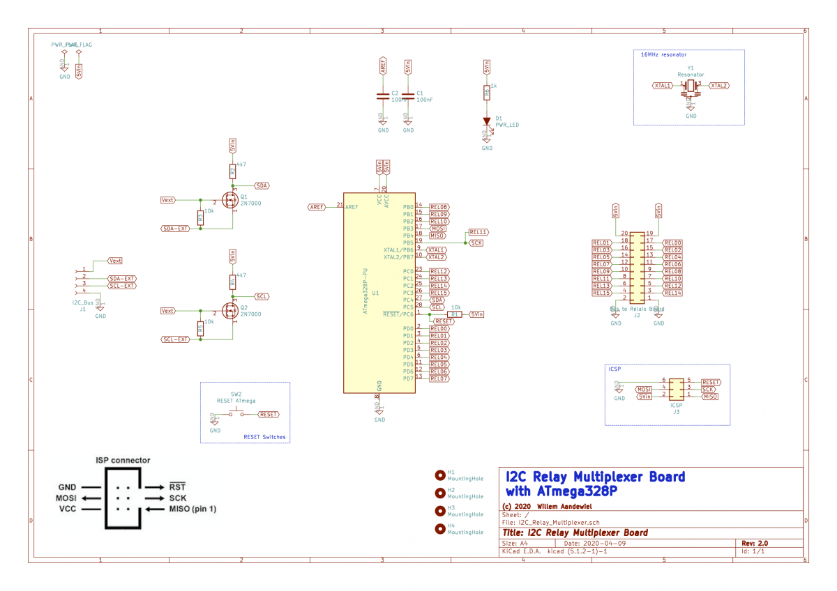
For the ATmega328P I wrote firmware so the ATmega can understand I2C commands and act accordantly to the commands given. As every I2C device it has registers you can read from or write to. The register map looks like this:
	registerLayout:
	  byte      status;         // 0x00 (RO)
	  byte      majorRelease;   // 0x01 (RO)
	  byte      minorRelease;   // 0x02 (RO)
	  byte      lastGpioState;  // 0x03 (RO)
	  byte      whoAmI;         // 0x04 (R/W)
	  byte      numberOfRelays; // 0x05 (R/W)
	  byte      Command;        // 0xF0 (W)
status is a read-only register (0x00) that holds the status of the multiplexer.
The major- and minorRelease registers (0x01 and 0x02) gives you information on the firmware release of the multiplexer.
The lastGpioState register (0x03) provides information on the state (HIGH/LOW) of the last used relay.
whoAmI is the register (0x04) that holds the I2C address of the multiplexer. The default address is 0x48 but you can change it to everything between 0x01 (1dec) and 0x7F (127dec). Once changed the new address is saved in EEPROM and that will be the new device address from then on (until you change it again).
numberOfRelays is the register (0x05) that holds, well, the number of relays on the used board. You can set this to 16 (for a 16 relays board) or 8 (for an 8 relays board). This value will also be saved in EEPROM.
To interface between your program (sketch) and the I2C Relay Multiplexer I made a library (I2C_RelaysMux).
This library has the following methods:
  bool    begin(Wire, deviceAddress);
  bool    isConnected();
  byte    getMajorRelease();
  byte    getMinorRelease();
  byte    getWhoAmI();
  byte    getNumRelays();
  byte    getStatus();
  bool    writeCommand(COMMAND);
  bool    digitalRead(relayNr);
  bool    digitalWrite(relayNr, {HIGH|LOW});
  bool    setI2Caddress(newAddress);  // 1 .. 127 (dec)
  bool    setNumRelays(numRelays);    // 8 or 16 (dec)
  void    showRegister(regSize, *regPtr, &Stream);
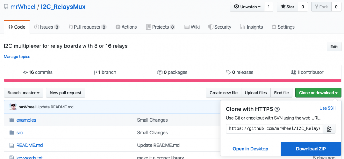
To use this library you first have to install it. From github download the library as a .ZIP file.
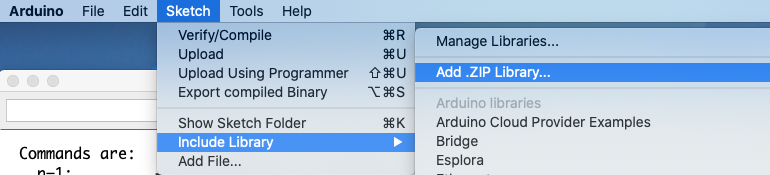
Then, in the Arduino IDE goto [Sketch] and then to “Include Library” -> “Add .ZIP library…”
In the popup window select the “I2C_RelaysMux-master.zip” file and click on the [Choose] button.
In your program you have to include the library with the following code:
 #include <i2c_relaysmux.h>
 I2CMUX          relay;     //Create instance of the I2CMUX object
In the setup() function you make the connection to the multiplexer:
	Wire.begin();
	if (!relay.begin(Wire, 0x48))
	{
	  Serial.println(“No device found. Abort!”);
	  while (true) {}
	}
You can now start using the multiplexer by sending instructions like this:
  relay.digitalWrite(2, HIGH);    // close relay 2
  state = relay.digitalRead(2);   // state should now be 1
  relay.digitalWrite(5, HIGH);    // close relay 5
  relay.digitalWrite(2, LOW);     // open relay 2
  for (int r=1; r<=16; r++)       // switch all relays HIGH
  {
      relay.digitalWrite(r, HIGH);
  }
The I2C_RelaysMux library with the ATmega firmware and two example programs are on github.
If you like this post please consider to give a donation
 Follow
I am the lucky user of one of the first prototypes of this board as I had to control 9 valves of my underground floor heating systems. The hardware and software work like a charm and keep my house comfortably warm 🙂 Together with a whole lot of other hard- and software we developed but more about that later!