[ 14,657 keer bekeken / views ]
In October 2017 I wrote a post with the title “Solid State Tape Device for the (micro)KIM“. Recently one of the makers (Dirk Dral) wanted to adapt the device for use with a genuine KIM-1 and ran into some problems.
His questions triggered me to pickup my microKIM and wonder what I could do to improve the design and the firmware. In the end Dirk came up with an as brilliant as simple modification for the KIM-1 himself but I already made a shortlist of the firmware improvements for version 2.0.
What the first design definitely misses is an easy way to upload and download programs from the SSTD to a computer. So that was put on the shortlist.
An easy way to work with the microKIM is by connecting the microKIM with a TTY cable to your desktop computer and then, a logical next step is to also operate the SSTD with your computer. Using a browser is the obvious choice.
In the mean time I also designed a 32 kb memory card for the microKIM (see this post) and using both the SSTD ánd the 32kb memory card makes sense. I designed a PCB for the SSTD that could be used directly on the microKIM or in conjunction with the memory card. As firmware is fluid and I was confident that rewriting the firmware would result in a working SSTD I sent the PCB designs to JLCPCB and started to work on the firmware.
Then I received an email from Dirk.
He had experienced errors while writing large programs to de SSTD. As it turned out the SSTD could only (reliable) save short programs. I never noticed that because I only have the (short) programs out of “The First Book of Kim”.
After investigating this I discovered a big design flaw in the original SSTD setup.
The SSTD consists of two processors. An ATtiny85 that extracts the bits out of the pulse-train from the microKIM. The bits (ones and zeroes) are then send to the ESP8266 who (left) shifts them into a byte and then the byte is written to SPIFFS as two ASCII chars (one byte is split into two nibbles and the binary value of these nibbles is converted to ASCII chars [0-9 and A-F]).
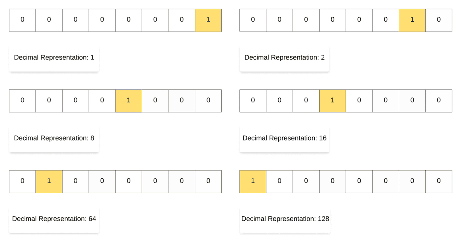
Bits arrive at a pace of 1 bit every 7 milli second.
After every 8 bits (approx. 60 milli seconds) two bytes are written to SPIFFS. That goes well for a while but eventually it takes more than 7 milli seconds to write to SPIFFS and then de ESP8266 misses one or more bits. From then on all the bits received are out of sync. To make things worse SPIFFS is depreciated and the replacement LittleFS is faster at reading from flash but slower on writing to flash ..
The solution is elegant and simple: Let the ATtiny combine the bits to chars and send the chars over Serial to the ESP8266. The ESP8266 now have approx. 60 milli seconds to write the bytes (and in the worse case the UART has a buffer so the ESP8266 can catch up later). So far so good.
For the prove of concept I tested the PLL firmware on an Arduino UNO and it worked flawlessly. As the ATtiny85 does not have a hardware UART I used a Software UART as implemented by the great “ATtinyCore” by Spence Konde. Albeit to no avail as the Software Serial implementation is of course interrupt driven .. and so is the detection of bits in the pulse train. And the two do not nicely live next to one another. After consultation with Spence I realised it needs an AVR processor with a hardware UART. The smallest ATtiny I have experience with that has a hardware UART is the ATtiny841. But that comes in a 16 pin package and is not pin compatible with the (8 pin) ATtiny85. So my first PCB design is useless and I have to make a new PCB for the SSTD.
Which I did.
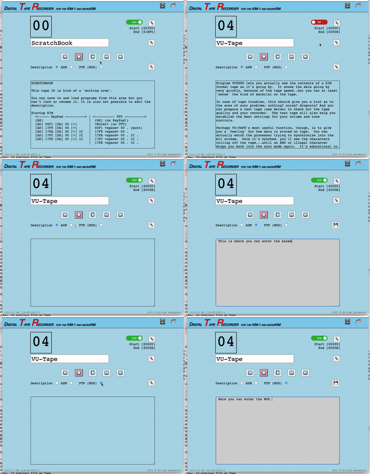
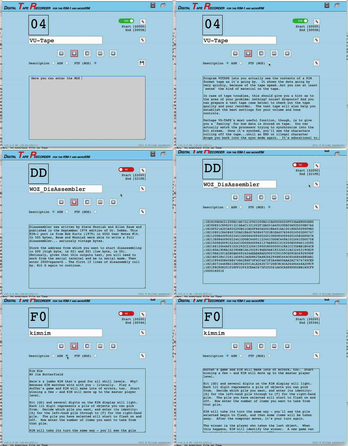
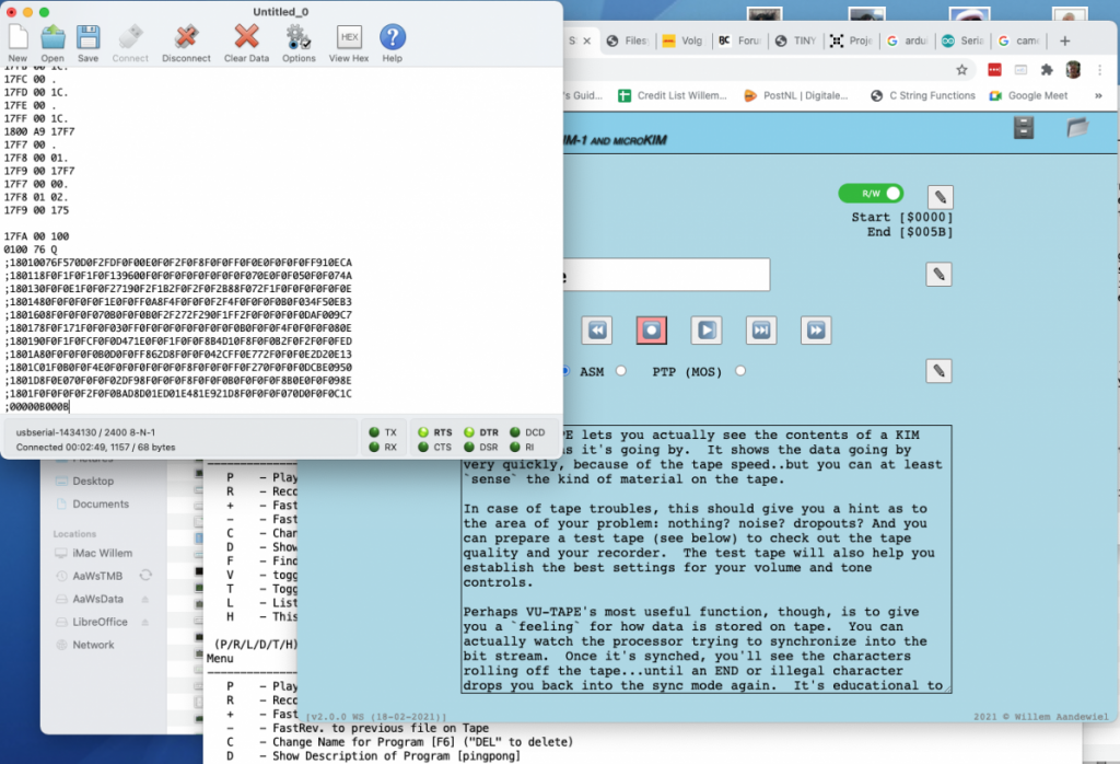
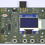
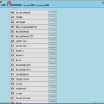
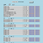
The new and improved 2.0 version of the hardware and firmware (that now is called “digital Tape Recorder” or “dTR”) imbeds a webserver that you can access via your browser (you can also access the dTR with telnet). It presents the same interface and information as the OLED display on the dTR and then some more.
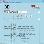
In every slot (program ID in hex) you can save a Program file (with the extension “.hex”), a Description (with the extension “.txt”) an Assembler listing (with the extension “.asm”) and a Paper tape listing in MOS Tech. format (with the extension “.ptp”).
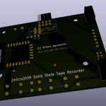
Building the digital Tape Recorder kit
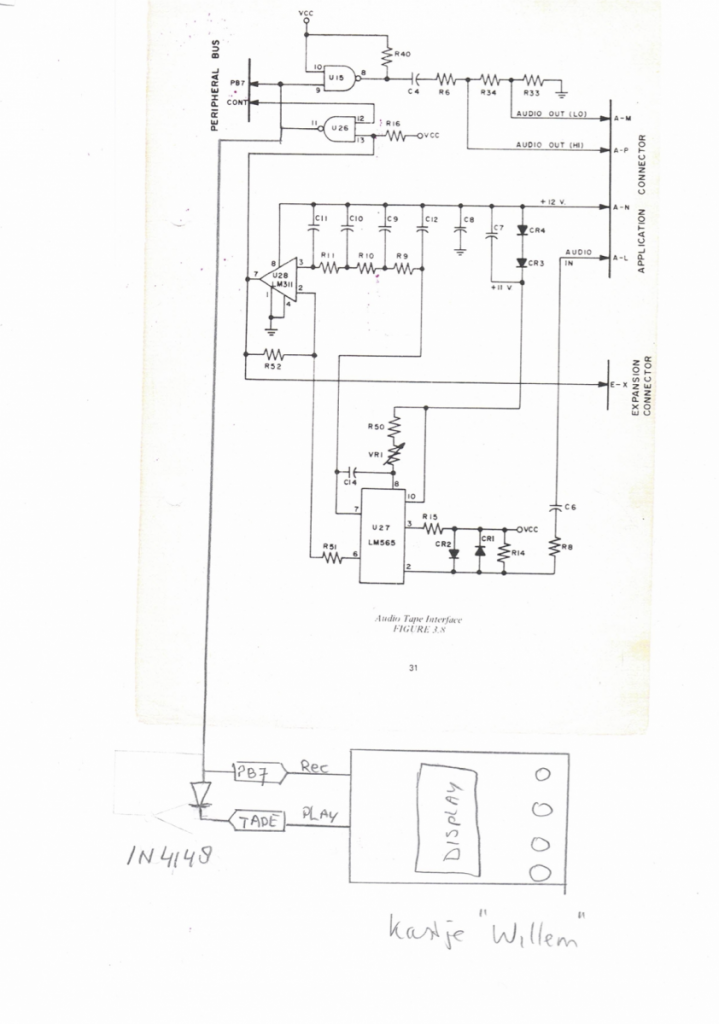
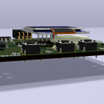
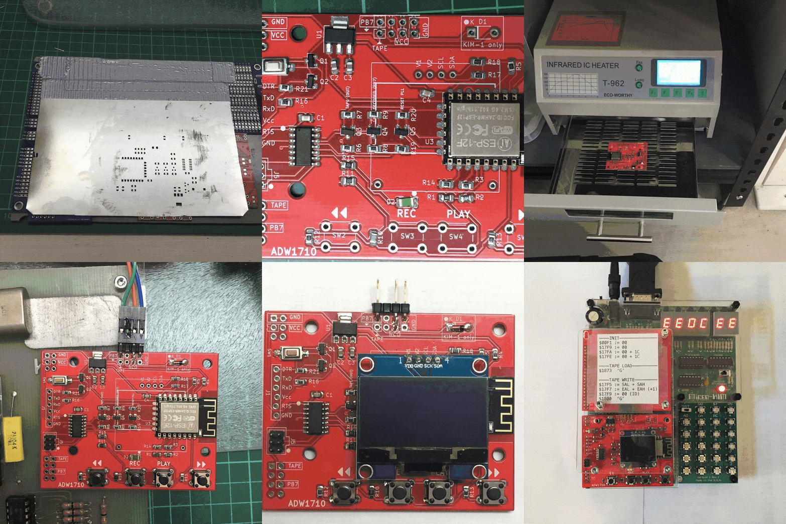
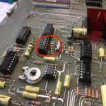
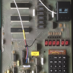
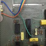
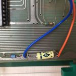
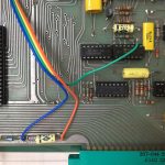
With the help of Dirk Dral the digital Tape Recorder can now also be used with a genuine KIM-1 (because PB7 of U2 is not on any of the extension connectors you do have to solder a wire on the KIM-1 to use the dTR).
The red vertical wire on the first image is PB7 (it’s the blue/green wire on the other images)
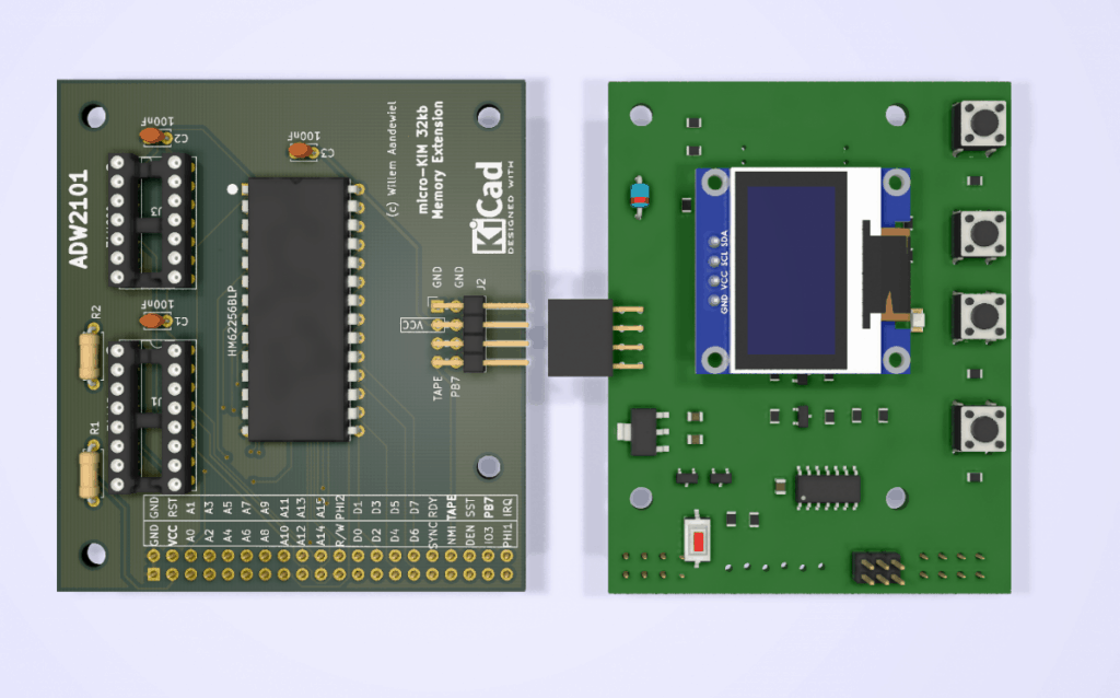
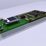
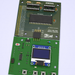
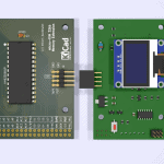
The digital Tape Recorder (ADW1710) is a great add-on for the microKIM and for the genuine KIM-1. You can plug it on the microKIM extension connector or you can use it in combination with the 32kb memory card (ADW2101). The memory card plugs in the extension connector and the digital Tape Recorder plugs in to the memory card.
With 32kb extra memory it gives your microKIM all the power you can ask for!!
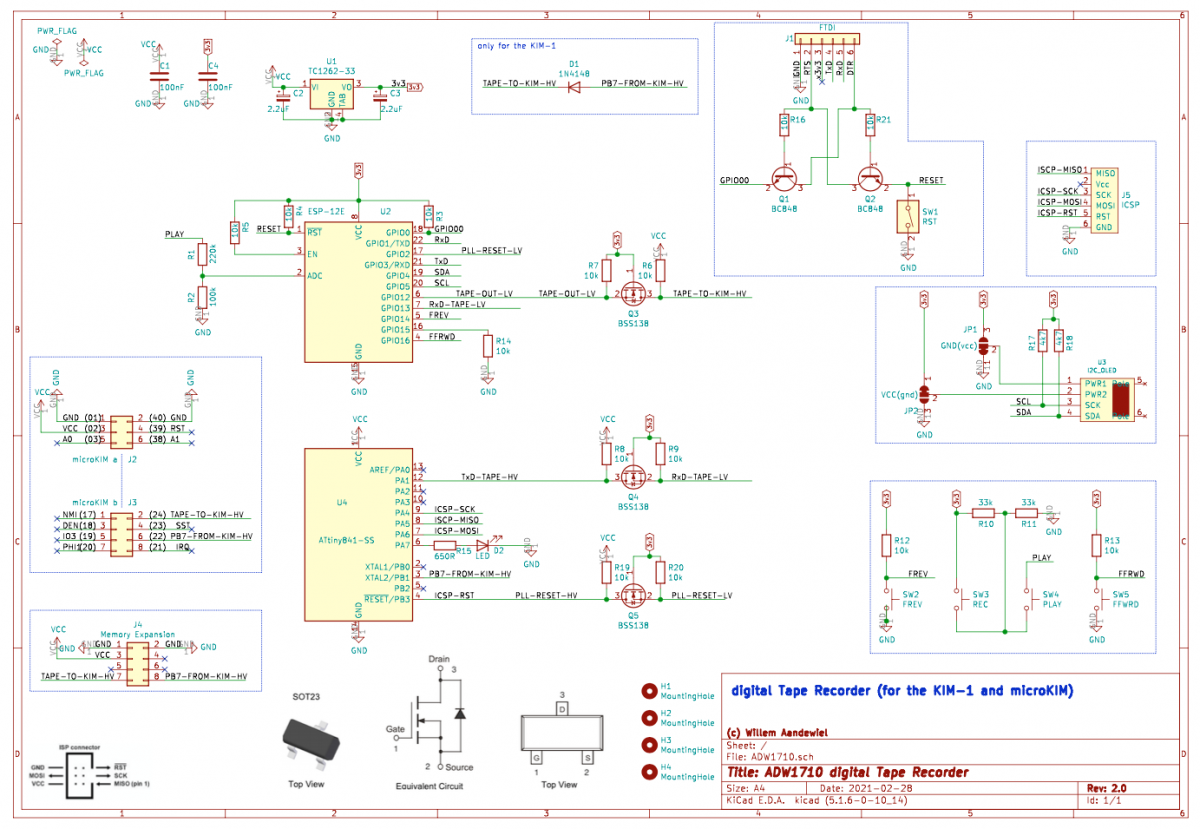
The 2.0 firmware is hosted on github.
Total costs for building this device is approx. € 35,40 (including PCB, OLED display and headers). Be aware: due to the limited space most of the parts are SMD.

 Follow
Hi Willem,
nice project. I am looking for this to use it at my KIM-1 Replica (not MicroKIM).
Where can i find gerber-files to build it, or is it not available ?
Thanks and greetings from Germany!
Markus
Markus,
Great you like the project!
I have added a “KiCAD” folder with the Gerber files and an Interactive BOM.
Great and Thanks, i will report, when i build this baby 😎
Yes, please do!
Btw: is the layout corrected because direction of diode who has wrong silkscreen direction?
So: solder as marked? 😀
Yes it is, but please check the traces (just to be sure)!
But you only need that diode if you want to connect the dTR to a genuine KIM-1.
so, Hardware is build, but the firmware … i don´t know how to build this up with Arduino IDE. I can´t update the boardmanager with ATTiny-Core, because the the certificate seems and of time and building “digitalTapeRecorder” has many missing library´s . and so on – many issues …
I don´t know, which library i have to install and so on …
Hi Markus,
To build the firmware for the ATtiny841 you have to install the ATtinyCore by SpenceKonde. But be aware that the URL to the github-repo’s now is encrypted so use “https” in stead of “http”!
All the settings you have to use in the Arduino IDE are in de `ATtinyPLL2.ino` and in the `digitalTapeRecorder.ino` files.
Libraries that are included with `#include <name.h>` are libraries you have to install using the Arduino IDE library manager.
Libraries that are included with `#include “name.h”` (like `#include “Debug.h”`) are part of the repo and are a [tab] in the Arduino IDE. You don’t have to install them.
If you still can’t work this out please write an other comment and we figure out what to do next.
After massive help from Willem and confusing Arduino-things, the Tape-Recorder works at a KIM-1 Replica ( :
First i have only tested to play something into KIM-1, Recording will come.
Thx to Willem for his help !!
Hello, I have a PAL-1 and would be interested in a pre-built one of these if you offer them for sale. I will pay appropriately to compensate you for your time building one.
Hi Robert,
I still have one PCB so I can build the Digital Tape Recorder for you.
I send you a PM
Very cool. Like others have commented, I would enjoy a kit but I can usually only swing a few SMD components per project.
If you have a schematic you could share I am inclined to create a through-hole version in KiCad.
Hi John,
Thanks for your comment.
The schematics are in the post as
.png(I can send you a.pdfif you want).SMD components are a bit scary at first, but I only use the biggest versions (1206) that you can easy hand solder (have done dozens of boards that way it myself).
Hi Willem,
I was wondering if you still have any PCBs for sale?
If not, would you post the gerber or Kicad files and I can get a board made.
I think your DTR will make using my Kim-1 replica a lot easier!
Many thanks
Russel,
I send you a PM.
Hello Willem,
I have a MicroKim and a PAL-1 and I would be very interested in buying a digital Tape Recorder PCB and a 32 kb memory card PCB.
Thanks in advance,
Eric
Quick question — what format HEX files are saved on the dTR?
Was trying to convert a paper tape file over and none of the converters I found were producing useful output.
Hi Jeremy,
Here you can find a convertor that does work. For Windows machines you have to take in account the extra ‘\r’ that Windows seems to need. Somewhere near line 150(?).
I made some minor updates to your program so that it will automatically handle Unix or Windows style line endings and fixed a bug with the output hex file name getting corrupted.
You’ve got a pull request open… but thank you very much for pointing me in this direction.
I designed a 3d printable case for this unit for those who want a bit more protections.
Available here.
Hello Willem..
Some years ago I followed your project, and tried to make a system for AIM65, with no succes.
1: Do you think it will work there?
2: Where can i find the PCB for the project?
I would love to have such a system tom my OLD AIM65.
Thank in advance..
Vy 73 de OZ6YM, Palle A. Andersen
Palle,
As both (KIM-1 and AIM65) are powered by MosTechnology they probably use the same method for reading and writing to tape.
You need to find the logic pin that reads and the one that writes the data without the analoge circuitry and than it will probably work.. but I have no experience with the AIM65 SBC.
Maybe you can ask Hans Otten.
I do have some PCB’s to sell.
Hello again Willem!
I would like to by a copy of your print.
How could we arrange that?
I normaly use PAYPAL paying on the net, and will prefer that.
How about you?
I will send you a PM
Hi there! Great little project.
Is this available as a kit or raw PCBs available? If not, are the gerbers available anywhere?
I’d love to add one to my PAL-1, and I’d love to support you if I can.
I send you a PM
Willem was so kind to build one of this cool devices for me and what shall I say: it’s the perfect add on for any Kim-1, Pal-1, micro-kim or other kim-clone.
Loading and saving from the KIM-1 on the dTR’s ESP microcontroller works like a charme, the Webinterface intuitive, and the shiny blue LEDisplay gives you all information you need.
Here is a little video that demonstrates the usage.
Thank you for the idea, the brilliant implementation and your support in the first days.
The webdokter is too kind!
He asked me to build a dTR for him because his smd soldering skills are a bit rusty. So I did.
But than he had to figure out why the device did not work! It seems I did not solder the ATtiny correct on the board (one pin was not connected) and so he had to upgrade his smd soldering skills after all.
Glad it worked out!
Hi Willem!
I’m a woodworker currently in a maker competition with the theme “iconic movie props”. I am building a Talkboy from the movie Home Alone 2 and would love to get it functional to digitally tape record. Can you help me out??
Thanks in advance!
-Justin
Hi Justin,
What would you like the dTR to do?
It is not usable for audio recording/playing.
Just wow.!!11 This is amazing and exactly what I am searching for. sadly my smd solder skills are non existant. I will have to wait until someone offers it as a kit or presoldered.
Hi Nils,
Nice you like it.
As a kit you still have to solder 😉
I can make one “pre soldered” for you if you want. I send you a PM.