[ 20,129 keer bekeken / views ]
Somehow, no matter what micro processor I choose, I end up with too few GPIO pins for the projects needs or for what I want to do.
For a recent project I switched from the ESP8266 to the ESP32 which has much more GPIO pins then his predecessor .. but still not enough.
To end this run for GPIO pins for once and for all I decided I needed a cheep extension board that could be configured for Switches (input) and LED’s or other stuff (output). And while at it I thought some extra logic would be nice.
So, what I came up with is a I2C extension board with eight GPIO pins that are freely configurable for input or output (I call the GPIO-pins “Slot’s“).
The extension board is specially well suited for use on a solderless breadboard. The schematic can later be incorporated with your hardware design.

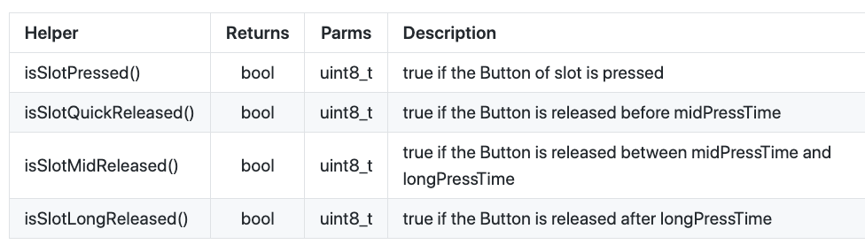
When configured as input-Slot the most probable use is for switches and then it would be great if we can distinguish a pressed button and the time between pressing the button and releasing it (quick release, mid release and long release). In the code on the main processor you can just say:
if (switch1 == pressed)
     do something();
if (switch1 == midReleased)
     do oneThing();
else do anotherThing();
For Slot’s that are configured as output it is more like a “shoot and forget” kind of Slot.
That is: you can say that the Slot must be HIGH or LOW like the digitalWrite() function in the Arduino IDE. But you can also say: Go HIGH for 2500ms and then go LOW again. In your main program you don’t have to write the code to wait for 2500ms and then switch the GPIO-pin LOW.
setOutputToggle(Slot, HIGH, 2500)
You can also tell the Slot to blink with an on-time and an off-time and, if you like, a duration. For instance:
setOutputPulse(Slot, 500, 1000, 10000);
The Slot will blink with 500 ms on, 1000 ms off over a period of 10 seconds (10000 ms) and stops blinking.
setOutputPulse(Slot, 500, 250, 0); // duration 0 is forever
The same as before but now the Slot will blink (500 ms on, 250 ms off) forever (or until you tell it to do something else);
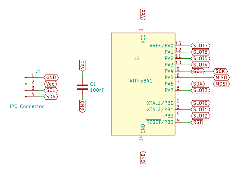
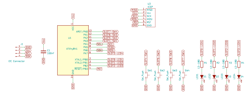
The hardware is designed around an ATtiny841 micro controller. Communication is by I2C (two wires, SCL and SDA). You can use the boards with 5Volt or 3.3Volt depending on your needs (most probably the voltage of the main processor) but you can not interchange 5Volt and 3.3Volt systems without some extra logic (level shifters for the SDA and SCL lines).
To interact with the ADW0720 boards I developed a library with simple commands.
Every I2C device has an address in the 1 to 127 (decimal) range. The default address for de ADW0720 boards is 0x18 (24 decimal) but you can change this to whatever you want with the command:
setI2Caddress(<newAddress>);
writeCommand(_BV(CMD_WRITECONF));
The second line saves this newAddress to EEPROM and from that moment on the newAddress is the address for this module. By giving every ADW0720 board a unique address you can control multiple ADW0720 boards with only the two I2C lines!
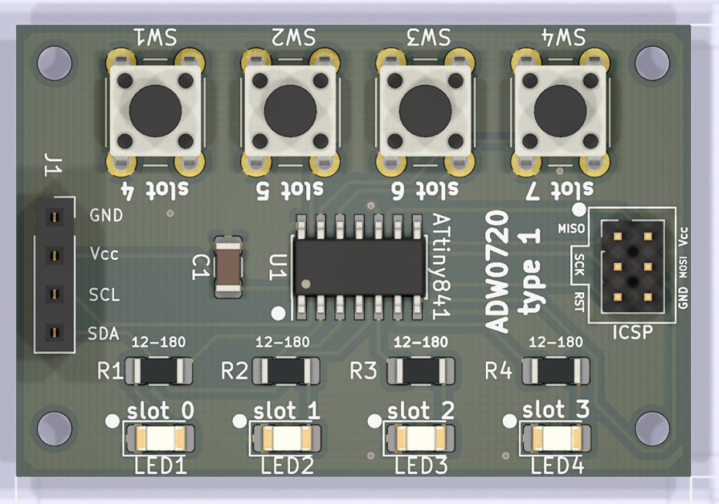
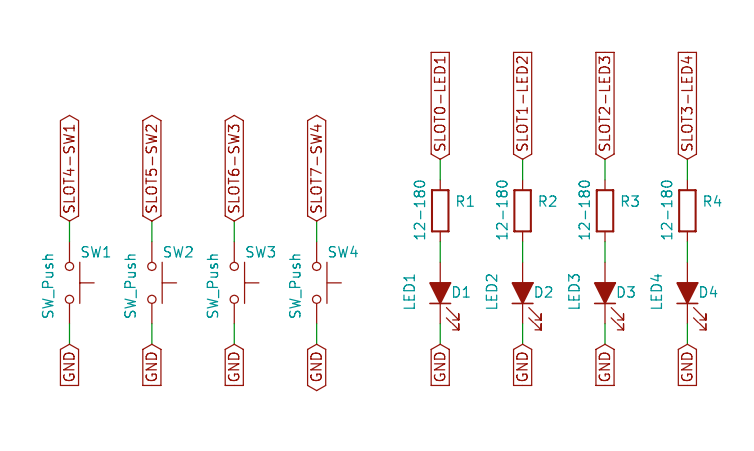
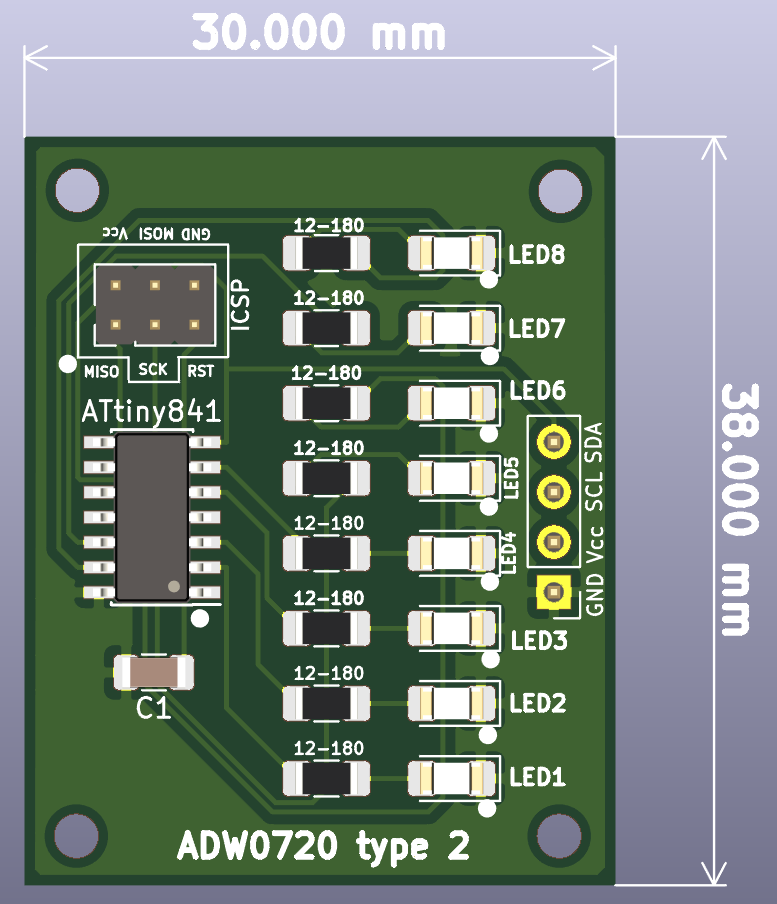
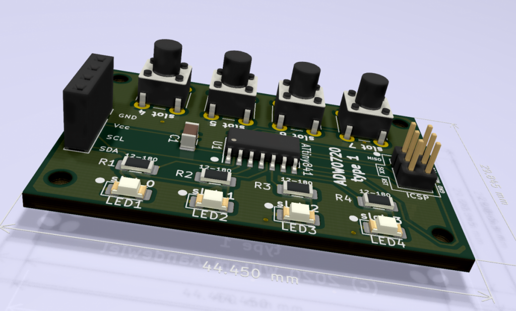
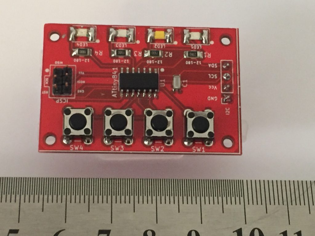
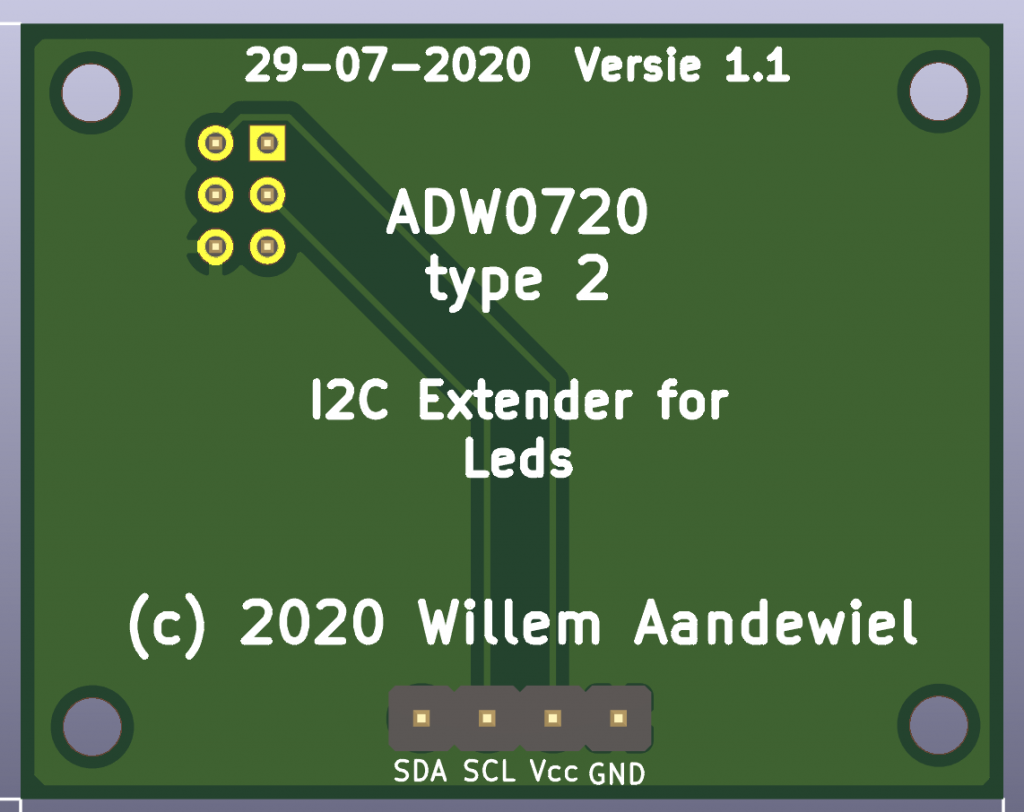
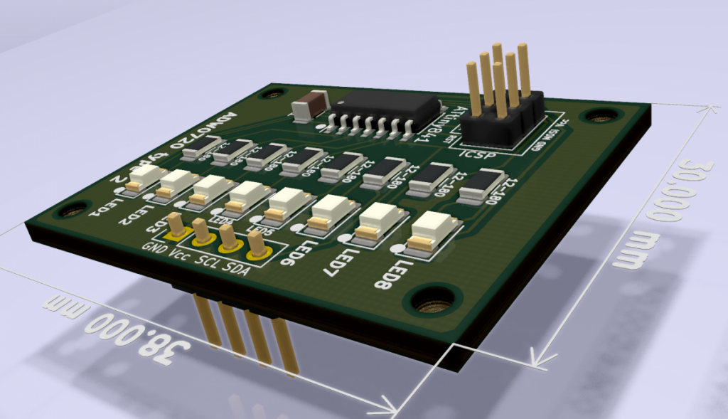
I designed two types of ADW0720 boards that are ready to use. The Type-1 board has 4 tactile switches and 4 LED’s, the Type-2 board has 8 LED’s but no switches.
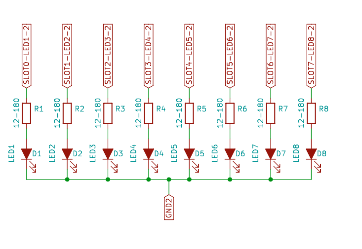
Type 2 with 8 LED’s 
Type 1 with 4 LED’s and 4 Switches
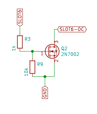
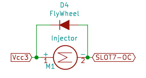
In stead of the LED’s it is also possible to control a N-channel MOSFET (like the 2N7000 or 2N7002) as a switch to control bigger loads like buzzers, relays or motors.

If you would like to have one of these boards but you don’t want to make them yourself, I have some that I can sell. Just write a comment with what you want (it won’t make me rich but it helps me to buy parts and develop other stuff that, hopefully, you like).
You can find the library and the code for the ATtiny841 slave on github. There you will also find the documentation for the library.
The library comes with two examples. The first one is just to show-off what the ADW0720 boards can do and the second one show’s more advanced usage. This second example (I2C_ADW0720_Configurator) can be used to setup the boards so you don’t have to do that in your main program (f.i. set the type of Slot for each of the 8 Slot’s and/or set the I2C address for the board at hand).


 Follow