
189 keer bekeken / views
This project was sponsored by
In an earlier post I described the development of an aerosol sensor that measures how much fine dust is present in the air and sends these values to an MQTT broker. The measured values can then, for example, be used to control the fan of a central ventilation system.
Hier kun je een Nederlandse vertaling van dit project vinden.
It is surprising to discover how much variation there can be in the amount of fine dust, depending on factors such as traffic, wood stoves, ventilation, or simply where you are located. That gave me the idea to build a small, portable device that allows me to take local measurements.
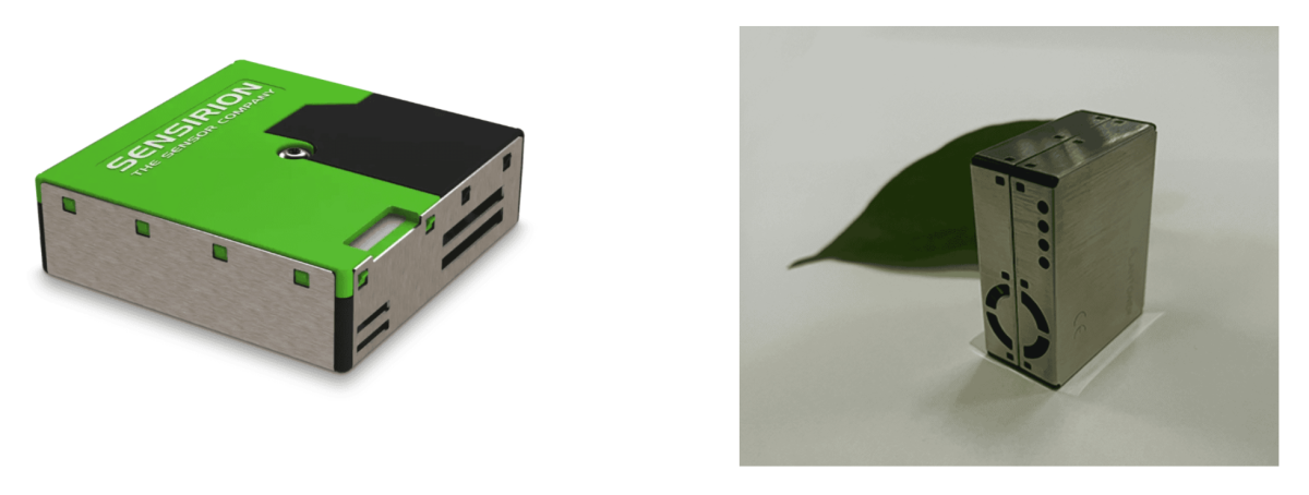
Instead of the PMS5003 sensor that I used in my previous design, I now want to use the SPS30 sensor (both sensors are made by Sensirion).
To truly be portable the design must meet a number of criteria:
- Because it is portable it must be powered by a battery or rechargeable cell
- Power consumption must be as low as possible when idle (when it is not being used) so the battery is not unnecessarily drained
- The measured data must be shown on a display
Design choices
- Instead of a complicated PCB design I want to use standard modules as much as possible.
- As a battery I will use a 18650 Li-ion cell. These are easy to obtain, have a large capacity and are not too big.
- As the central processor I will use an ESP32 board. These have sufficient memory and processing power for the sensor.
- At first I considered using deep sleep when the device is not in use. However, most ESP32 boards still consume several tens of milliamps in deep sleep, often because of the LDO. Therefore I looked for a way to completely disconnect the unit from the battery and only connect it when the device is actually in use (and thus measuring).
The solution is a so-called soft latch circuit. With this circuit, using a p-channel MOSFET, the power between the battery, the ESP32, the sensor and the e-Paper display is completely disconnected. Power consumption in the “off” state is only a few microamps.
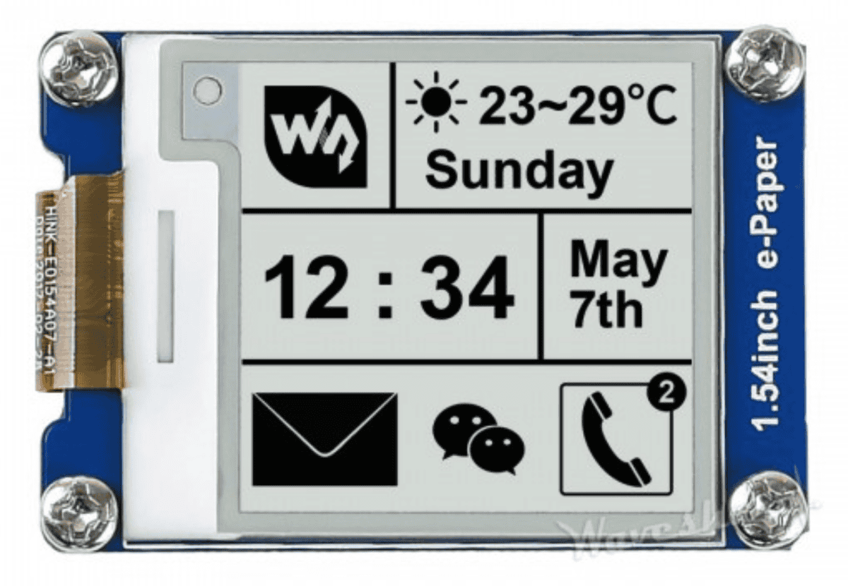
- To display the measurement data I need a display, but most displays only show data when power is applied. To use as little power as possible I want the device to switch off once it has finished measuring. That would normally mean the measurement can no longer be read. The solution is an e-Paper display. With these displays the information remains visible even when the power is turned off.
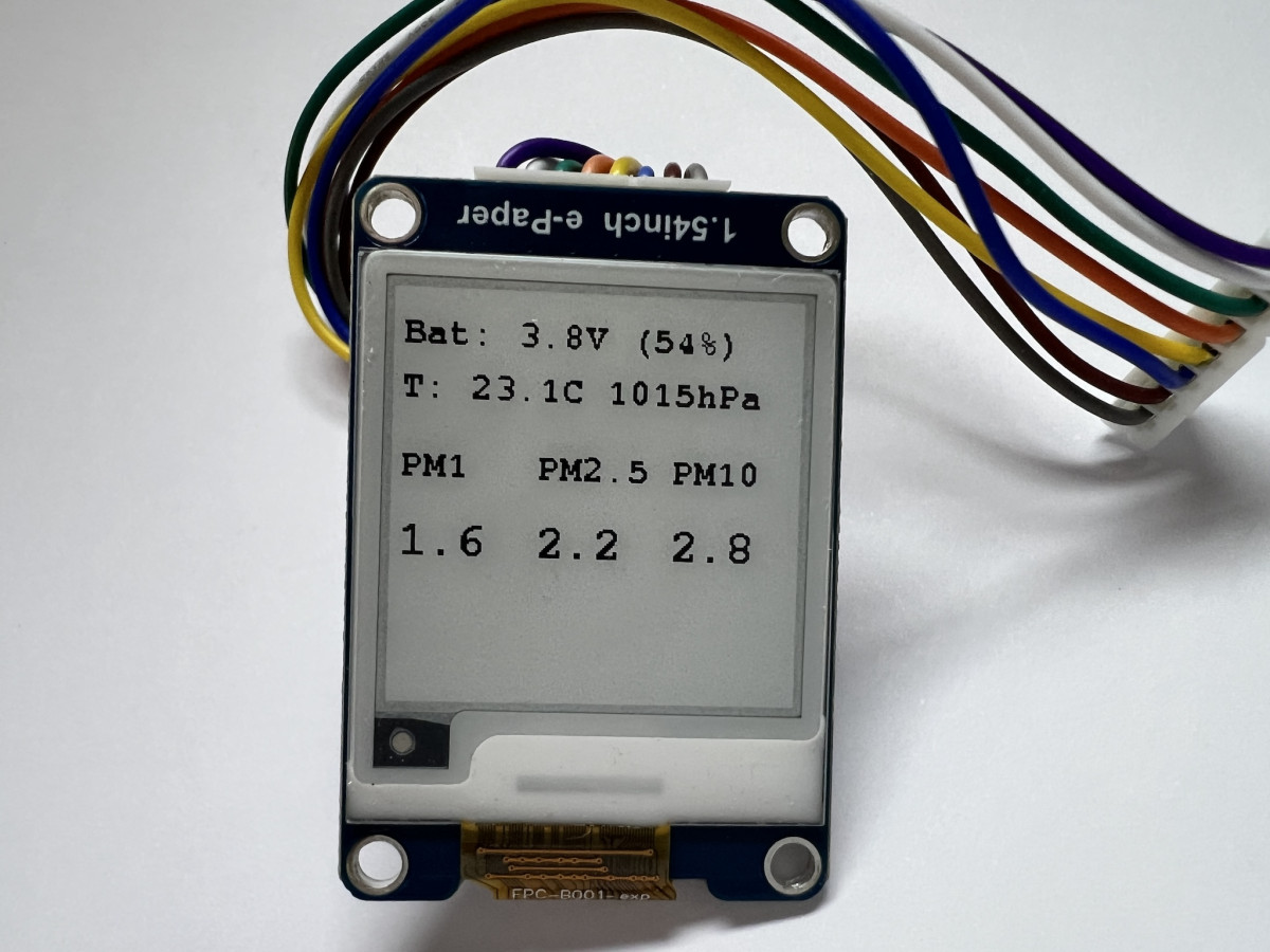
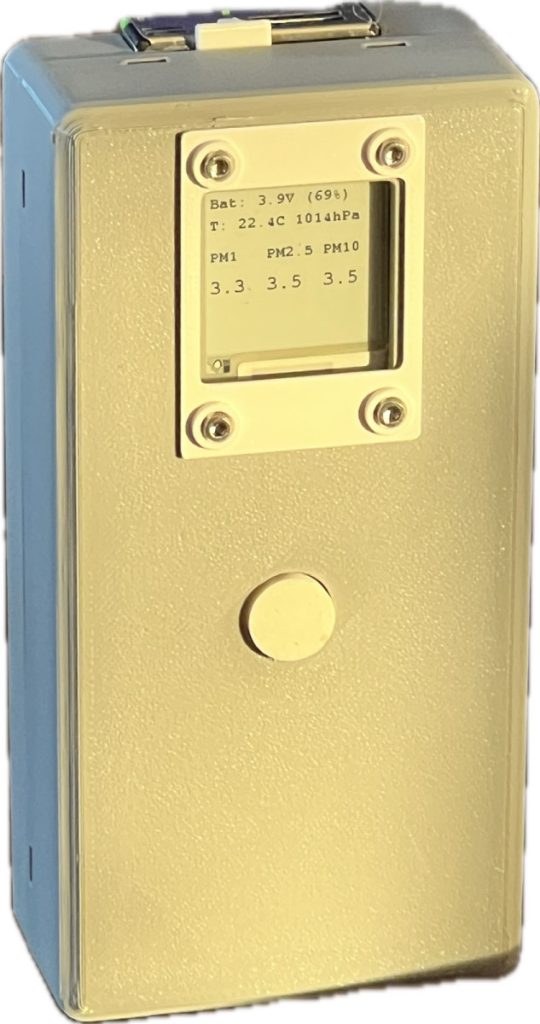
The result is a handheld fine dust meter based on an ESP32 and a Sensirion SPS30 sensor with an e-Paper display. The device is intended for quick measurements at a location: outside in the street, inside the house, near an open window or for example in a workshop. Because the device runs on a battery it is truly portable and handheld.
The SPS30 sensor
The SPS30 sensor measures the mass concentration of fine dust in several fractions: PM1.0, PM2.5 and PM10. These are the concentrations of particles smaller than 1 µm, 2.5 µm and 10 µm respectively.
The sensor uses a laser and a fan to draw air through a measurement chamber and count the particles. This produces fairly reliable readings.
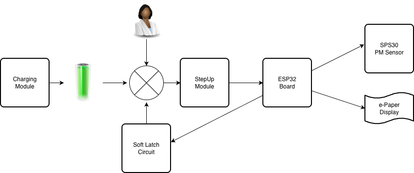
The basic design
As mentioned earlier, I want to use standard modules as much as possible. In this case:
- a module that can charge the 18650 cell
- a soft latch circuit
- a step-up converter module that converts the voltage from the 18650 (~2.5 V – 4.2 V) into a stable 5 volts
- an ESP32 board as MPU
- a 1.54” Waveshare e-Paper display
Charging module
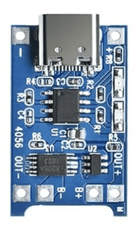
The charging module is a very common one (I bought several for a few euros each from Amazon).
DC-DC step-up module
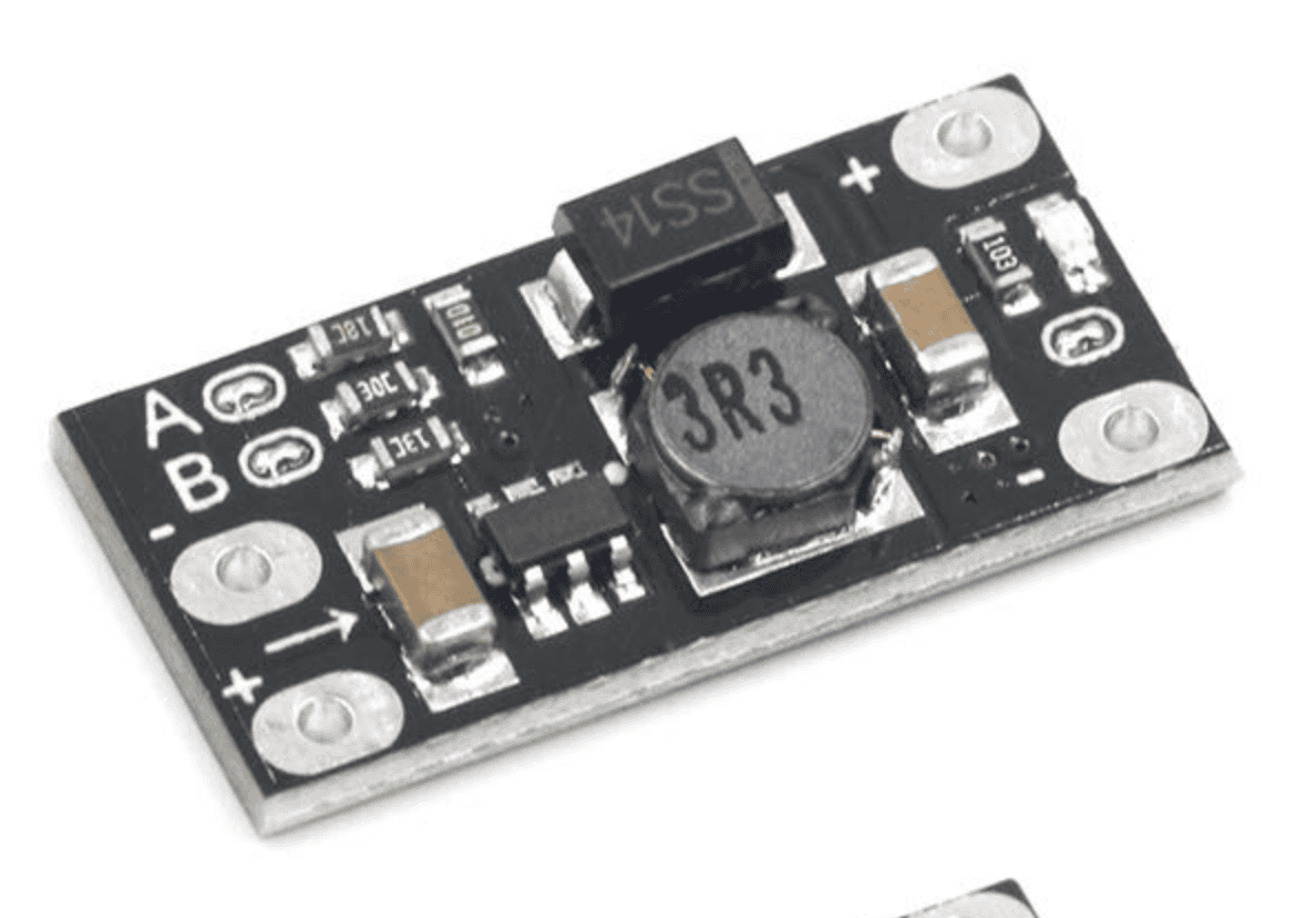
I also bought this module from Amazon for a few euros.
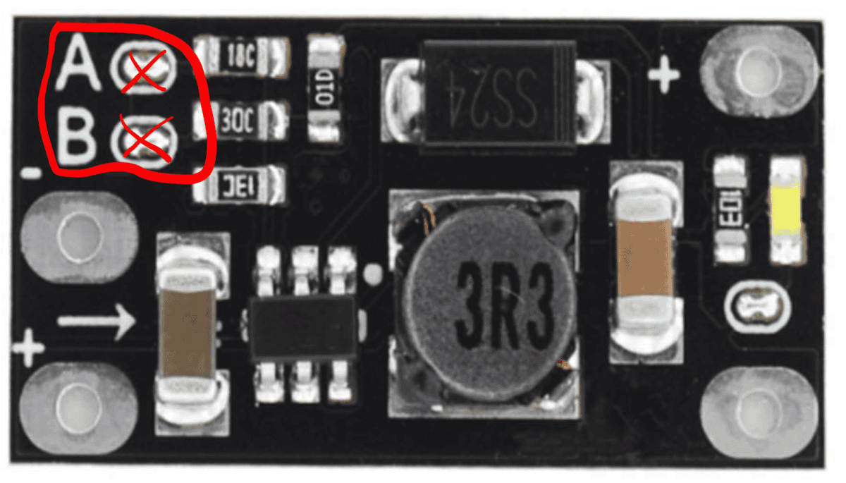
Note that the module can produce several output voltages (5 V, 8 V, 9 V and 12 V).
To obtain an output voltage of 5 volts the two 0-ohm resistors (next to A and B) must be removed.
Do not forget!
SPS30 (or PMS5003) fine dust sensor
The SPS30 particulate matter sensor is made by Sensirion.
Waveshare 1.54” e-Paper
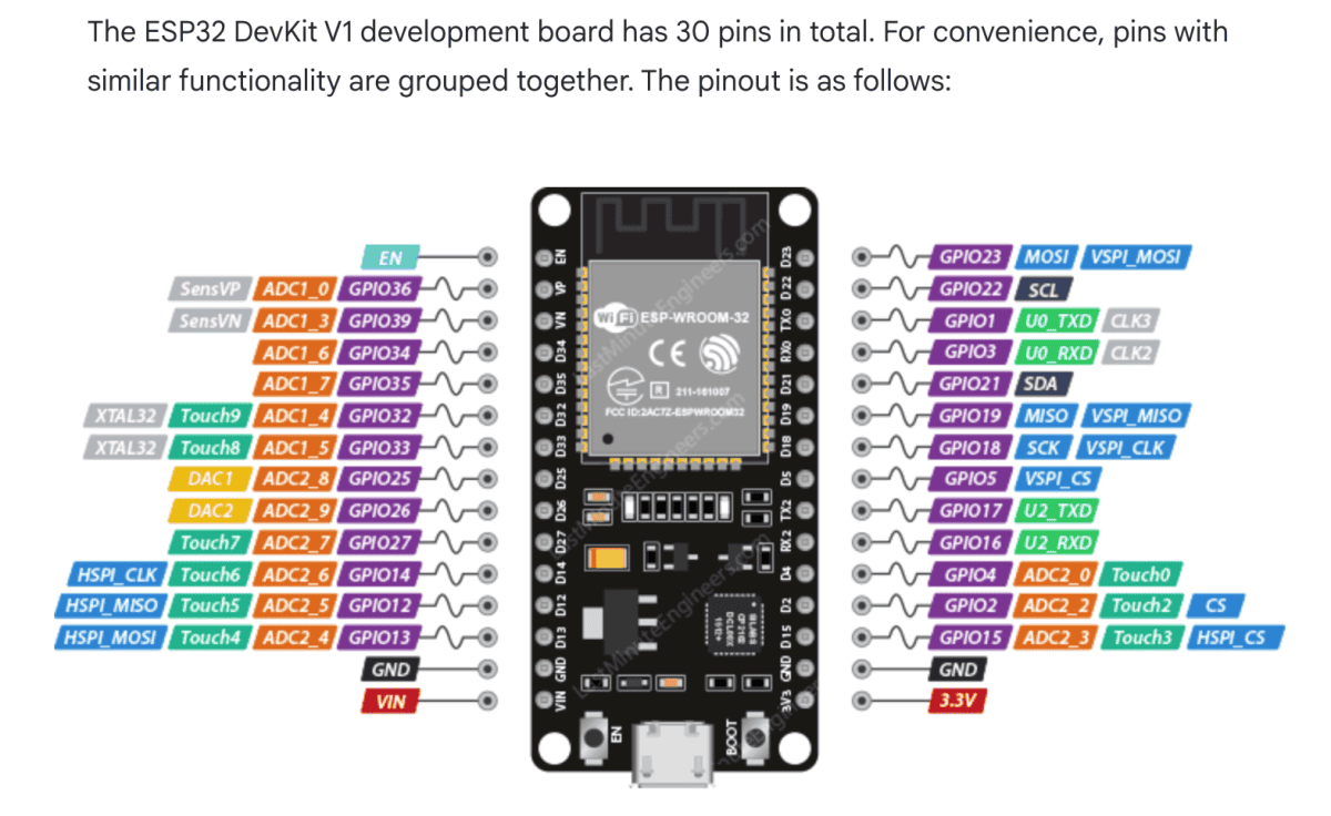
ESP32 DevKit 30-pin
There are literally dozens of different ESP32 boards available. For this project and the PCB I based the design on a 30-pin ESP32-DevKit-V1 board.
Global operation of the device
When the button (SW1) is briefly pressed, Q101 starts conducting and the ESP32, the SPS30 and the e-Paper display receive power.
The ESP32 will first set the latch pin (GPIO_PIN_LATCH) HIGH. This keeps the circuit latched so Q101 continues to conduct.
The SPS30 sensor and the e-Paper display now also receive power.
For reliable measurements the SPS30 must first warm up. This warm-up time is configurable (via the platformio.ini file). According to Sensirion the warm-up time must be at least 30 seconds.
After this warm-up time the device performs five measurements (also configurable), which are shown directly on the display. Finally the average of all measurements is displayed and the ESP32 sets the latch pin LOW. Q101 switches off and the power is disconnected.
Simplified code example
void setup()
{
  // -- Switch off WiFi and Bluetooth as early as possible
  // -- This saves power and avoids starting hardware that is not needed
  disableRadios();

  // -- Keep the power latch active so the device stays on
  digitalWrite(pinLatch, HIGH);

  // -- Initialize the display and prepare the first screen contents
  epdInit();

  // -- Read battery voltage early
  // -- If the battery is too low, show a message and shut down
  batteryVoltageLast = readBatteryVoltage();

  if (batteryVoltageLast < 3.4f)
  {
    switchOff("BATTERY TOO LOW");
    return;
  }

  // -- Initialize shared communication buses
  // -- I2C is used for the SPS30 and optionally for the BMP280
  i2cInit();

  // -- Detect which sensor hardware is available
  // -- The code can work with more than one particle sensor type
  detectAvailableSensors();

  // -- Try to start the particle sensor measurement
  // -- When successful, the software enters the warm-up phase
  if (!particleSensorInitAndStart())
  {
    messageText = "Particle sensor error";
  }
  else
  {
    messageText = "Warming up...";
  }

  // -- Reset all software timers used by the state machine
  restartTimers();

}   // setup()


void loop()
{
  // -- Run small background jobs that must be serviced regularly
  // -- Example: button handling, display housekeeping, sensor polling
  serviceBackgroundTasks();

  // -- If a shutdown was requested somewhere else in the code,
  // -- execute it here as soon as possible
  processSwitchOffRequest();

  // -- Run the main application logic
  // -- This is the state machine: warm-up, sample, validate, average, show result
  runMainStateMachine();

  // -- Check again after the main logic,
  // -- because the state machine may have requested a shutdown
  processSwitchOffRequest();

}   // loop()
The soft latch circuit
For correct operation the soft latch circuit is a crucial component. Many variations can be found on the internet, some better than others. After some research I ended up with the following circuit:
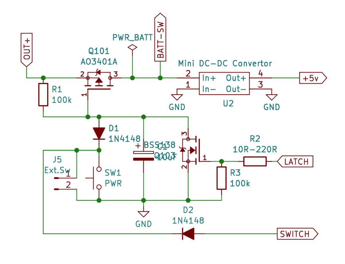
It consists of two MOSFETs:
a p-channel MOSFET (AO3401) used as the power switch and an n-channel MOSFET (BSS138) for control.
Two signal diodes (1N4148) are included so that the push button, after power has been applied, can also be used as a normal switch on GPIO33.
Dave from EEVblog and PKAE Electronics have made videos explaining how the circuit works.
How good is this soft latch circuit?
To test this I connected a timer output to the “Ext.Sw” jumper (J5) and repeated the following cycle 700 times:
• close for one second (which starts the fine dust measurement cycle)
• open for two minutes (within this time the sensor switches itself off again)
Starting with a fully charged 18650 cell, after those 700 cycles the cell voltage was still above 3.8 volts (about 50%).
Quite efficient!
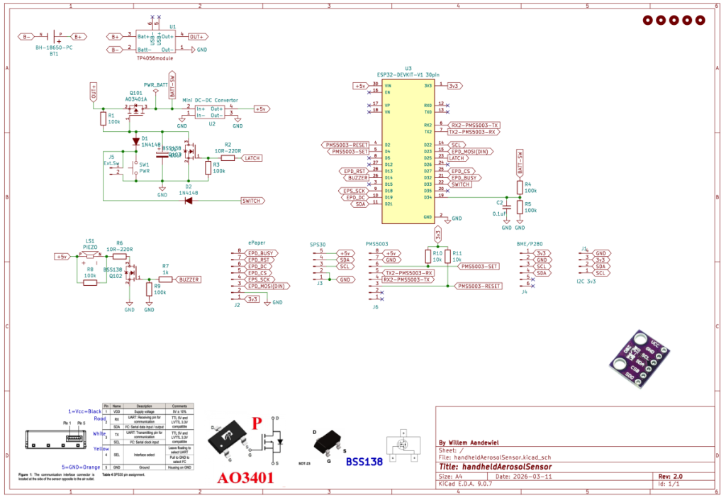
Here is the complete schematic of the handheld fine dust meter:
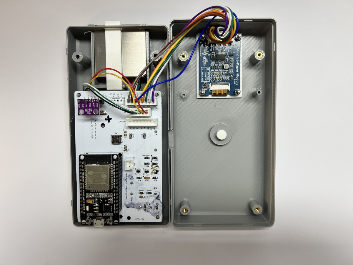
PCB
Using KiCad I designed a PCB with space for most of the components. Only the SPS30 and the e-Paper display are not mounted on the board but can be connected with standard 2.54″ pin headers or JST-XH connectors.
On the top side of the PCB:
- the 30-pin ESP32 module
- the soft latch circuit
- the push button
- the connector for the e-Paper display
- connectors for the SPS30 sensor or optionally the PMS5003
- space for a BME280 (air pressure and temperature)
- an I²C connector
On the bottom side of the PCB:
- the 18650 battery
- the charging module
- the step-up converter module
- a piezo speaker


Ordering the PCB
After designing the PCB, the design (in the form of Gerber files) must be sent to a PCB manufacturer.
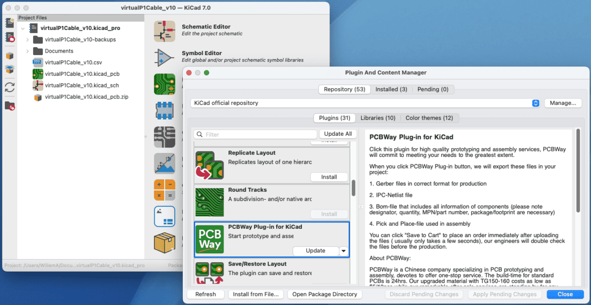
I like to use and KiCad has a nice plugin that automates this process. The plugin is called “PCBWay”.
Installation is done via the Plugin and Content Manager of KiCad.
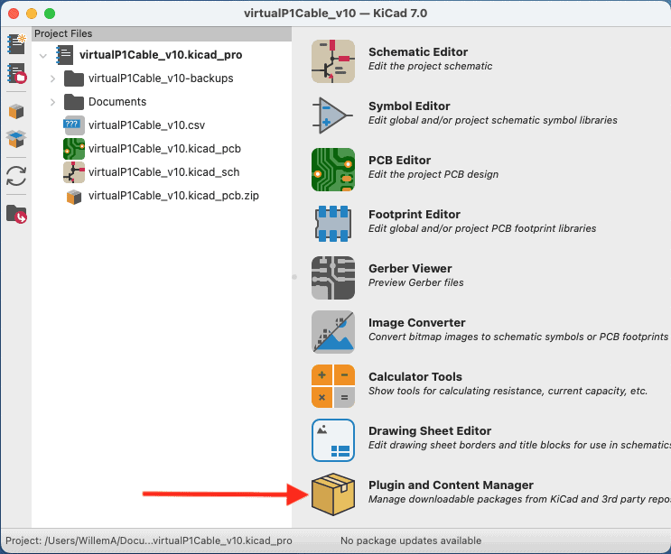
After installation the KiCad toolbar has a new button.
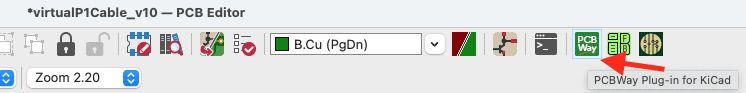
By clicking this button all required files are packed into a .zip file and the browser opens the PCBWay website.
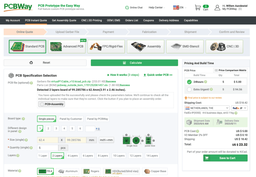
You then specify how many boards you want to manufacture and how you want the board to look (solder mask color and silkscreen color).
After inspection by the engineers you can pay the manufacturing and shipping costs.
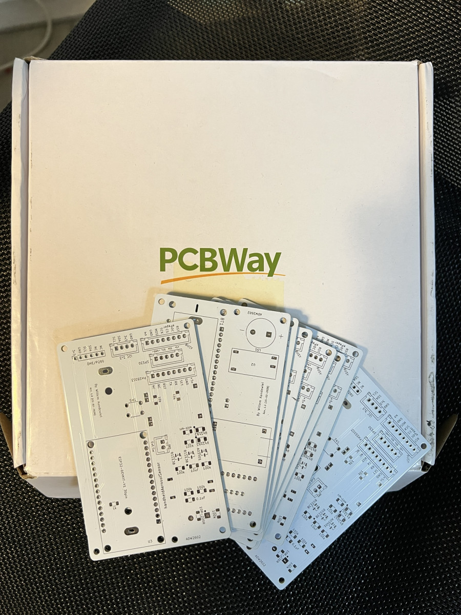
After about a week the PCBs are delivered and arrive in your mailbox.
Assumptions are not always helpful
In my KiCad installation there was no symbol or footprint for the AO3401 or the BSS138. I wrongly assumed that all SOT-23 MOSFETs would have the same symbol and footprint.
That turned out to be incorrect.
After soldering the first board and applying power, the ESP32 immediately turned on. Strange. Pressing the button changed nothing.
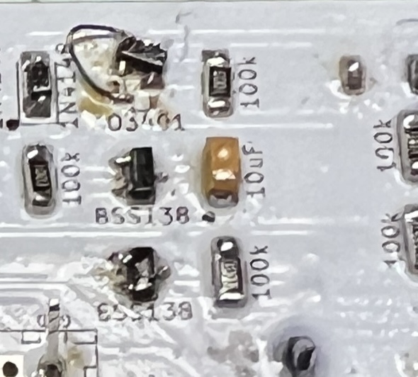
After further investigation I discovered that MOSFETs are not all identical. By soldering the AO3401 slightly tilted with a short wire on the PCB and mounting the BSS138 upside down (because drain and source were swapped) everything worked as intended.
I fixed this in PCB revision 2.0. I also slightly moved the two outer connectors and changed the placement of the BME280 connections.
One final thing
The device can actually do a bit more than described above.
For example, when starting up and just before shutting down the ESP32 measures the voltage of the 18650 cell and displays it. This is important because a Li-ion battery can be permanently damaged if the voltage drops below 3 V.
If the voltage drops below 3.5 V the display shows the message:
Battery LowIf the voltage drops even further the device shuts itself down as quickly as possible (without performing measurements). The display then shows:
Battery Error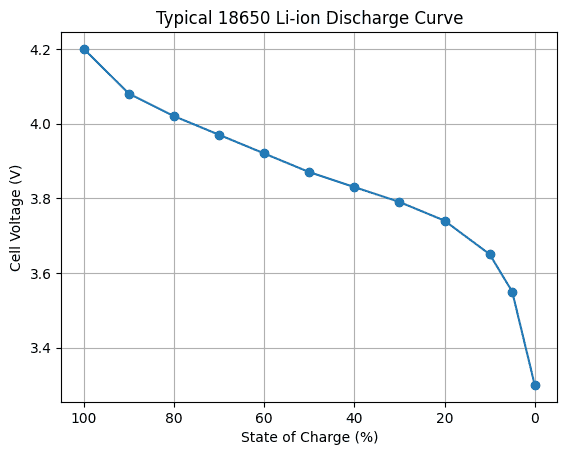
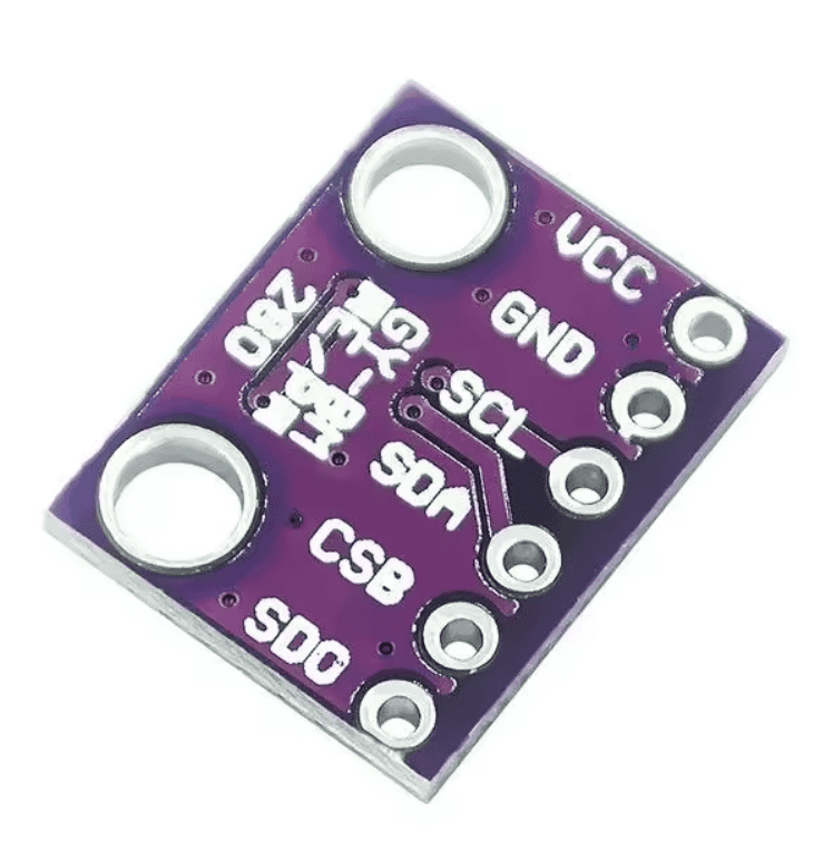
Besides reading the SPS30 it is also possible to mount a BME280 on the PCB. If such a module is present the measured temperature and air pressure will be displayed when the device starts and shuts down.
Because WiFi and Bluetooth transmitters are immediately disabled at startup to save battery power, I needed a way to still perform OTA updates on the ESP32.
By pressing the button (SW1) three times during startup the device will connect to a known access point. If no connection can be made a WiFi manager will be started.
The display will show:
          WiFi Portal Started
          Waiting for User Input
          HHPMS-<MAC-Address>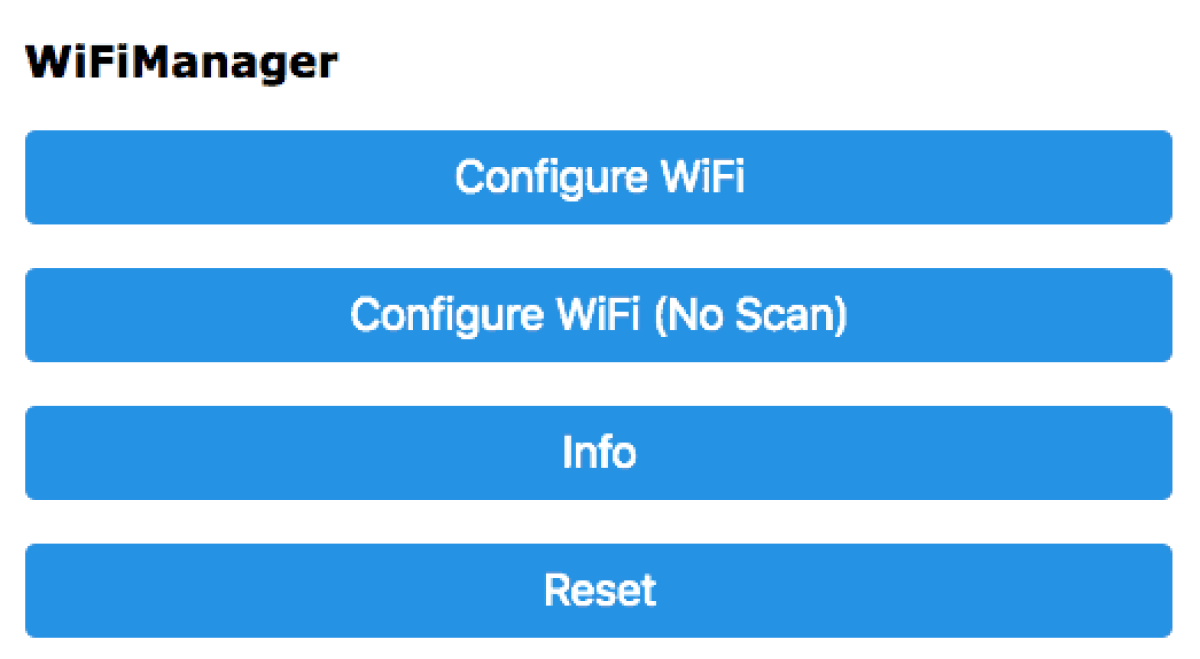
Now click [Configure WiFi] and select the access point named “HHPMS-A4B5C6” (A4B5C6 are the last three bytes of the ESP32 MAC address and are different for each chip).
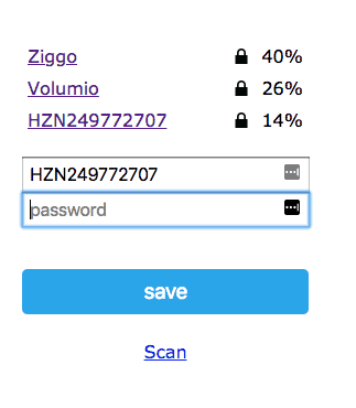
You must then connect your computer, tablet or phone to this access point and enter the credentials of your own WiFi network.
After clicking Save the data will be stored in the ESP32 and it will try to connect to this network in the future.
The display will now show:
WAITING FOR UPDATEStart the OTA update and the display will show:
UPDATINGAfter the update the device restarts and begins the normal measurement cycle, after which it shuts itself down again.
The PCB and the software support both the SPS30 sensor and the PMS5003 sensor. If the device does not detect an SPS30 at startup it will automatically switch to a PMS5003.
If that one is not present either, the message
NO SENSORappears and the device shuts itself down.
All design files and software can be found in this repository.
 Follow