
This post has 5,959 keer bekeken / views
Sometimes the internal Watchdog Timer (WDT) of a MCU is working more against you than that it ‘helps’ you. Also an internal WDT is not always up to the task of resetting the main MCU to a known state.
Especially the ESP8266 has some quirks that makes it reboot for not-always-obvious reasons but fails to restart the MCU when needed. And if your house warming system depends on a ‘twenty four seven‘ working system the External Hardware Watchdog Timer (EHWDT) I describe in this post can be very handy.
The objective is to have a means to monitor activity on a master processor, for instance, an ESP8266 (or ESP32 or any other type of processor). The master processor needs to have a ‘hartbeat‘ signal that can be fed to the EHWDT. This can be done by toggling a GPIO pin on- and off. For visible feedback you can add a LED to this GPIO pin so you can monitor the hartbeat.

The master processor needs to send at least every _MAX_HALF_SECONDS seconds a “Keep Alive” pulse to the WatchDog [WDT-FEED] (a 3v3 signal is level-shifted by Q1 to [WDT] (PB2, DIL-7)). If the WatchDog does not receive this pulse in time it will make [ESP-RESET] (PB3, DIL-2) HIGH for 500 msec to reset the master processor.
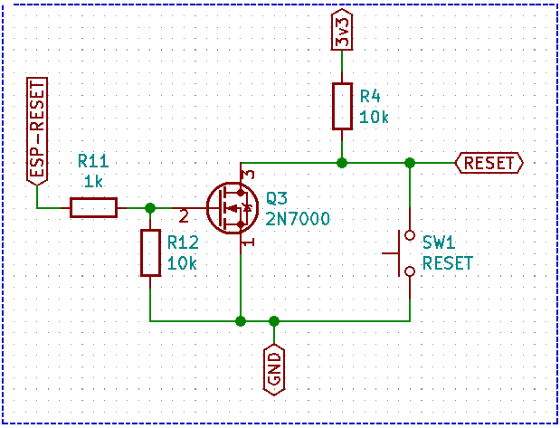
In the image above you see a typical reset circuit for an ESP processor. [ESP-RESET] comes from the ATtiny85 (PB3, DIL-2). The Q3 MOSFET works as a level-shifter (if needed) and on a HIGH signal it will pull [RESET] down.
PB4 (DIL-3) on the ATtiny85 is used to control (in this case) a relay but if you don’t need a relay you can remove this part of the circuit (Q2, R5 and R6). PB0 (DIL-5) outputs a signal to the [WDT-LED] (D2) which will, after every received “Keep Alive” pulse go “HIGH” for 500 milliseconds).
Two seconds before the circuit will reset the master processor the PWM_LED will blink rapidly.

You can find the source for the ATtiny85 WDT on github as an Arduino Sketch.
Boot sequence:
==============
 State       | REL_LED | SGNL_LED      | Remark
 ------------+---------+---------------+-------------------------
 Power On    | Blink   | Blink         | Inverse from eachother
             |         |               | Relays "Off"
             |         |               | Next: "Fase 1"
 ------------+---------+---------------+-------------------------
 Fase 1      | Off     | 900 MS On     | repeat for 25 seconds
             |         | 100 MS Off    | Relays "Off"
             |         |               | Next: "Fase 2"
 ------------+---------+---------------+-------------------------
 Fase 2      | Off     | 500 MS On     | wait for 3 Feeds to pass
             |         | for every     | Relays "Off"
             |         | Feed received | Next: "Fase 3"
 ------------+---------+---------------+-------------------------
 Fase 3      | Off     | Blink Fast!   | wait for 3 Feeds to pass
             |         | for 2 seconds | Relays "Off"
             |         |               | Next: "Normal Operation"
 ------------+---------+---------------+-------------------------
 Normal      | On      | 500 MS On     | Relays "On"
 Operation   |         | for every     |
             |         | feed received |
             |         +---------------+-------------------------
             |         | Blink fast    | If no feed within 2
             |         |               | seconds:
             |         |               | Next: "Alarm State"
             |         |               | else: "Normal Operation"
             |         |               | Relays "On"
 ------------+---------+---------------+-------------------------
 Alarm State | Off     | Off           | Relays "Off"
             |         |               | Reset ESP8266
             |         |               | Restart ATtinyWatchDog
             |         |               | Next: "Power On" state
 ------------+---------+---------------+-------------------------
During the ‘power on‘ fase there is some visible feedback during witch time the master processor needs to settle. First the SGNL_LED and the REL_LED blink a few times. Then the REL_LED dims and the SGNL_LED blinks for 25 seconds. After that the EWDT waits for three hartbeat pulses from the master processor. Now ‘normal operation‘ is started and the EWDT is ‘armed‘.
If the SGNL_LED starts blinking fast it means that the master processor did not send a hartbeat for more than two seconds and both the master processor and the ATtiny85 will reboot.
 Follow