Part-2 – The Electronics
This is part 2 of the four parts posts about the DONOFF ecosystem.
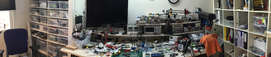
In this part I will try to explain the electronics.
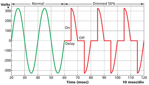
The hundreds of posts on the internet about mains dimmer designs all use a triac to cut-off part of the sine waves of the AC mains. Some do this by leading-edge cut-off, where the first part of the sine wave is cut-off:
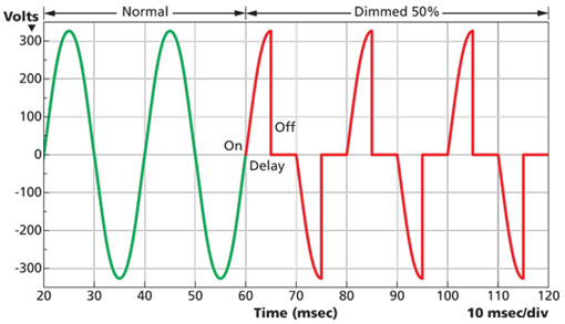
Another method is by trailing-edge cut-off where the last part of the sine wave is cut-off:
As elegant and nice as these solutions may be, they only work with resistive loads (incandescent lights). You can, at least in the Netherlands, no longer buy incandescent lights and in the near future the only lights available will be LED lights.
You cannot dim LED lights by either trailing- or leading-edge cut-off! But (dimmable) LED lights can be dimmed with Pulse Wide Modulation (PWM). PWM switches the power to the LED light on and off at a (relatively) high frequency.
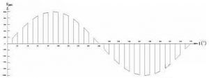
The DONOFF hardware uses this PWM to dim the (dimmable) LED lights but PWM can also be used to dim incandescent lights (So as a bonus, DONOFF can also dim incandescent lights).
A widely discussed PWM dimmer design on the internet is based on the design by Ton Giesberts. There are countless refinements on his design like the one from diy_bloke . I have used these designs and refinements as a basis for DONOFF.
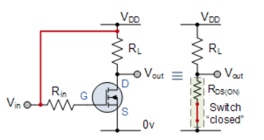
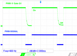
DONOFF uses a MOSFET to switch the power on and off at a (modest) high frequency. You can look at a MOSFET (very simplified) as an On/Off switch. The switch is closed by adding a positive voltage (Vin > 10 Volt) to the gate of the MOSFET. Remove the gate voltage (Vin = zero) and the switch is open. In the open state (Vin = 0 Volt) the internal resistance of a MOSFET is (simplified) infinite, in the closed state (Vin > 10 Volt) the (Rds) resistance (still simplified) is zero ohm. In both states there will be no power dissipation and heat build up! It is important though that the transition between “open” and “close” is as short as possible because the MOSFET will dissipate power during that transition
Before you continue reading: please read the warning!
Warning
Do not build this design as it will probably kill you in the process and burn your house down while using it. After that it will explode!!
I’m not joking! This project uses deadly voltages and you should only build it if you’re a qualified electronics engineer. If you decide to build it, it will be your responsibility to take the necessary precautions – I’ll take no responsibility whatsoever for your actions in implementing it. Even more, I am NOT a qualified electrical engineer, thus I offer no warranties for the design or the fitness of this design to your purposes.
The complete circuit

The electronics consist loosely out of five subsystems. I will briefly address each one of them.
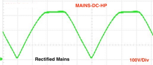
Mains AC to DC
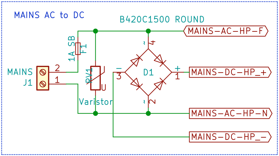
The design uses a MOSFET to control the intensity of the (LED) light. As MOSFET’s only work with Direct Current (DC) this part of the circuit rectifies the 240 volt AC (RMS) into ~330 volt DC (pp). The fuse (F1) will limit the current of the circuit to about 1 ampere. RV1 is an ‘over voltage protection’ that will dissipate spikes so they will not damage the rest of the circuit.
In the schematics you will find labels [MAINS-DC-LP] (Low Power) and [MAINS-DC-HP] (High Power). You will also find those for AC. These labels are connected to each other but are needed for KiCAD to create different trace widths.
MOSFET control circuit
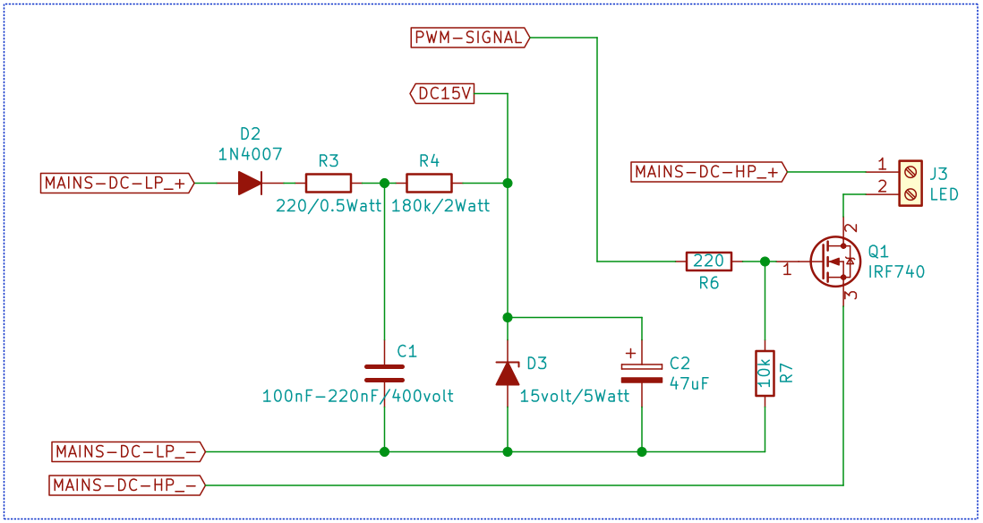
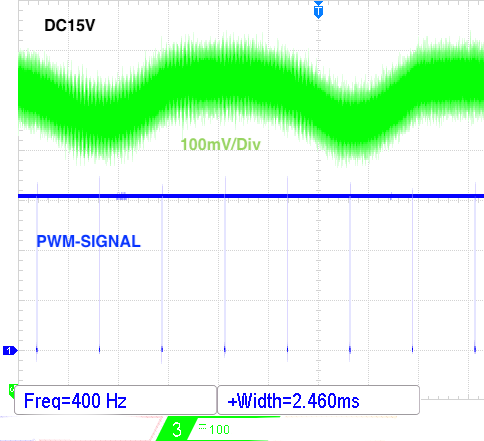
This is the heart of the DONOFF hardware. D2, D3, R3, R4 and C2 functions as a 15 Volt small current power supply to drive the gate of Q1. The MOSFET gate is normally pulled low by R7 (MOSFET switch “open” – LED light is Off). To close the MOSFET the optocoupler will pull the gate to 15 Volt (MOSFET switch “closed” – LED light is On). The Optocoupler (U1), R6 and R7 draw about 2.2mA (15v/(220+6800)). C2 will buffer the energy and is protected by the D2 against discharge when the rectified voltage goes below 15 Volt. Together with the D3 Zener, the group will keep a voltage between 12.5 – 15 Volt to drive the gate of Q1 (Q1 is fully closed with a gate voltage Vgs > 10 Volt). The ripple is about 150 milliVolt when the PWM is at almost 100% (worst case).
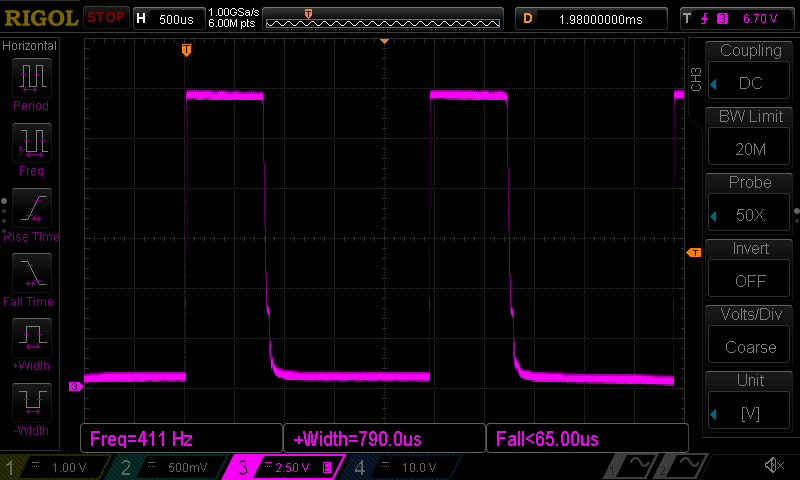
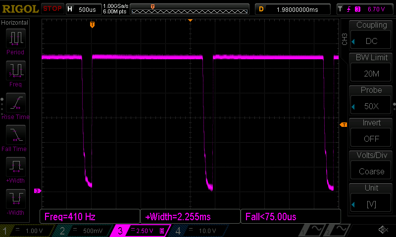
Voltage normally at 15 Volt, but drops a bit to about 13 Volt at 100% PWM and maximum gate open
Be aware that the current flowing through R4 is also 2.2mA which in turn results in 0.7 Watt (I2 * R = 4.8 * 150) that will be converted to heat (the temperature of R4 will rise some 15°C above ambient). Thats why R4 is a 400 Volt 2 Watt resistor (a little bit over dimensioned).
R6 is to protect the optocoupler and Q1 by limiting the gate current.
C1 is to filter the ‘MAINS‘ DC voltage.
Optocoupler

The optocoupler U1 isolates MAINS from the ESP-01 electronics. The PWM signal comes from the ESP-01 microprocessor and turns the infrared diode on and off. When the diode is on the transistor in the optocoupler will conduct between the Collector and the Emitter (and will in turn pull the gate of the MOSFET to 15 Volt, which will switch the MOSFET “on”).
ESP8266 Microprocessor
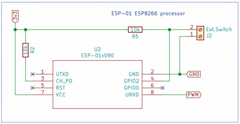
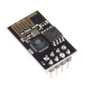
The DONOFF is controlled by an ESP8266 (ESP-01 board) microprocessor. The main reason for using the ESP-01 (and not f.i. an ESP-12) is the fact that you can pull the ESP-01 out off the DONOFF dimmer to program, thereby reduce the chance to get electrocuted whilst connecting the wires from a programming device to the DONOFF dimmer. But of course, the DONOFF can also be programmed ‘Over The Air‘ (without a physical connection)!
The ESP-01 has one input (GPIO2) for an external switch and one output (GPIO3/URXD) that provides the PWM signal to the optocoupler. There is a built in LED at GPIO1. The ESP-01 is powered by a 3v3 power source.
ESP8266 3v3 DC power
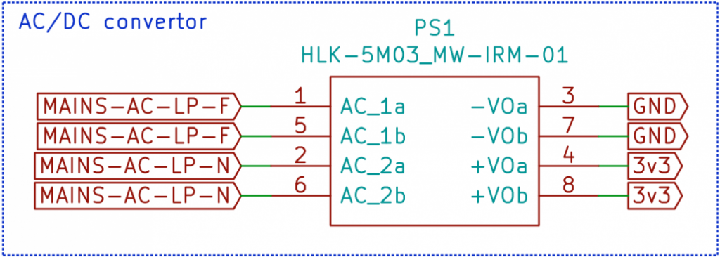
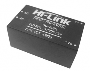
For ease of use and safety the DONOFF uses a solid-state power supply from Mean Well (IRM-01-3.3) or from Hi-Link (HLK-PM03) to power the ESP-01 with 3v3.
 Follow
Hi Willem!
Thank You for the project! Greetings from Ukraine (Bucha district)!
Very interesting, I will try to reproduse by myself (have some skills of power supply development&manufacturing for Kyiv subway and little skills of AVR ASM programming in late 1990th). My goals: to control lighting, boiler and Electric Vehicle Supply Equipment which requires 1 kHz pilot PWM 10-50%. So question: how can I change PWM Freq to 1000 Hz? I have found in Donoff.ino: uint16_t localPWMfreq = 250; // Hz but here stated “Well, the PWM frequency in Hz. A value between 200 and 900.”
Thank You in advance!
Gennadiy.
Hi Gennadiy,
Nice you like my project.
I have no experience in the field you try to make this project work. The frequency range of 200 to 900Hz is for normal dimmable LED bulbs. But I suppose you can use 1000 for your special case.
Good Luck!
Thank You!
So, what should I change for 1 kHz PWM? Is limit 900 Hz hard-coded or simply proposed by interface but not limited? For Your general understanding how Electric chargers work, You can search AnalogEVSE simple project, schematic diagram nice and simple (requires analog comparators, for 1 kHz PWM generation I will try to use ESP8266 instead of HEF4060 with quartz and RC integrator) but works with many EV/PhEV:
Renault ZOE (all models)
Hyundai IONIQ electro
Mercedes B-Class ED
BMW i3
BMW i8
BMW eDrive
Tesla Model S, 3 and X
Smart ED (old and new model)
Toyota Prius Plugin
Kia Soul EV
VW Passat GTE
VW Golf GTE
VW E-Up!
VW E-Golf
Nissan Leaf
Audi A3 e-tron
Opel Ampera-e
Look here.
Bedankt je reactie. Ik zal een kitje bestellen en bouwen. Dan ga ik eens kijken of het ook met Tasmota werkt. Ik houd je op de hoogte van de resultaten.
– Nog een andere vraag. De DONOFF firmware is die ook in bin formaat beschikbaar, of moet dit speciaal met Arduino IDE geflashed worden. Zelf bezit ik geen arduino hardware.
Mello,
Ik kan wel een binary voor je maken en naar je opsturen.
Graag, dat zou erg fijn zijn. Mijn email adres is bekend.
Alvast bedankt.
Beste Willem,
Een mooi project, deze dimmers. Gebruik al jaren Sonoff devices met Tasmota firmware. MQTT en Domoticz. Kan deze dimmer ook met Tasmota in Domoticz geintergreed worden?
Hi Mello,
Ja, dat kan (vast wel).
Hi Willem,
Je hebt hier geen ervaring mee, begrijp ik?
Nee, ik heb er geen ervaring mee, maar de Sonoff schakelaars die ik ken hebben intern gewoon een esp8266. Ik heb een paar daarvan van de Donoff firmware voorzien en dan werken ze op het Donoff systeem.
Het zal dan ook niet heel ingewikkeld zijn om een Donoff dimmer geschikt te maken voor Tasmota of Domoticz.
Hoi Willem,
Hoe zit het in dit schema met de afstraling van radiogolven?
Ik kan me voorstellen dat een pwm puls op 230 volt storing kan veroorzaken zeker wanneer de draden naar de lamp langer worden.
Groetjes Jeroen
Ik heb geen last van “radio golven” kunnen constateren. Ook geen meldingen hierover ontvangen.
Hoi Willem,
Bij het compeleren met Arduino IDE krig ik op lijn 879 (httpClient.begin(wifiClient, URL); // Specify request destination) de volgende fout melding;
C:\Users\jackp\Documents\ArduinoData\packages\esp8266\hardware\esp8266\2.4.2\libraries\ESP8266HTTPClient\src/ESP8266HTTPClient.h:144:10: note:   candidate expects 4 arguments, 2 provided
C:\Users\jackp\Documents\ArduinoData\packages\esp8266\hardware\esp8266\2.4.2\libraries\ESP8266HTTPClient\src/ESP8266HTTPClient.h:146:10: note: bool HTTPClient::begin(String, uint16_t, String, bool, String)
     bool begin(String host, uint16_t port, String uri, bool https, String httpsFingerprint)  __attribute__ ((deprecated));
          ^
C:\Users\jackp\Documents\ArduinoData\packages\esp8266\hardware\esp8266\2.4.2\libraries\ESP8266HTTPClient\src/ESP8266HTTPClient.h:146:10: note:   candidate expects 5 arguments, 2 provided
exit status 1
no matching function for call to 'HTTPClient::begin(WiFiClient&, String&)'
Ik heb alle libs geinstalleerd (denk ik…) en kom met googelen / dit forum niet verder.
Waar ik de mist in?
Merci, jack
Jack,
Volgens mij heb je álles goed gedaan.
Ondertussen is de firmware ook getest met de ESP8266 core versie 2.6.x en ik raad je aan om die laatste core versie te installeren en dan kijken hoever je komt.
Success!
Hoi Willem,
Success, met 2.6.3 kan ik nu compilen en uploaden.
Volgende probleem is de data upload, krijg de volgende melding;
esptool: error: unrecognized arguments: --end
SPIFFS Upload failed!
[SPIFFS] data    : C:\Users\jackp\Documents\Arduino\DONOFF\data
[SPIFFS] size    : 128
[SPIFFS] page    : 256
[SPIFFS] block   : 4096
/admin.html
/admin_sm.png
/favicon.ico
/index.html
/lightOff.ico
/lightOn.ico
[SPIFFS] upload  : C:\Users\jackp\AppData\Local\Temp\arduino_build_953398/DONOFF.spiffs.bin
[SPIFFS] address  : 0xDB000
[SPIFFS] reset    : --before no_reset --after soft_reset
[SPIFFS] port     : COM3
[SPIFFS] speed    : 115200
[SPIFFS] python   : python.exe
[SPIFFS] uploader : C:\Users\jackp\Documents\ArduinoData\packages\esp8266\hardware\esp8266\2.6.3\tools\upload.py

usage: esptool [-h] [--chip {auto,esp8266,esp32}] [--port PORT] [--baud BAUD]
               [--before {default_reset,no_reset,no_reset_no_sync}]
               [--after {hard_reset,soft_reset,no_reset}] [--no-stub]
               [--trace] [--override-vddsdio [{1.8V,1.9V,OFF}]]
               {load_ram,dump_mem,read_mem,write_mem,write_flash,run,image_info,make_image,elf2image,read_mac,chip_id,flash_id,read_flash_status,write_flash_status,read_flash,verify_flash,erase_flash,erase_region,version}
               ...
esptool: error: unrecognized arguments: --end
SPIFFS Upload failed!
Ik heb Phyton 3.7 en 3.8, esptool versie 1.0.3 en 1.0.4 geprobeerd met hetzelfde resultaat.
Moet ik iets anders installeren?
Merci,
jack
Jack,
Google is je beste vriend!
Zoek op “
esptool: error: unrecognized arguments: --end“ en je vind tientallen redenen waarom je deze fout krijgt en hoe je hem moet oplossen!Hi Chris en anderen:
Ik heb ook mn eerste set gebouwd en hij werkt!
Maar, de lampen (LED Dimable verschillende soorten) branden allemaal niet stabiel. Ze faden, afhankelijk van de PWM-frequentie, regelmatig aan en (deels) uit. Het lijkt of er een klokpuls net uit de pas loopt met de netfrequentie of zo. Misschien een zero-cross probleempje? Kan iemand mij advies geven?
Groet, RobV
Hi RobV,
Heb je verschillende PWM frequenties geprobeerd?
De meeste LED lampen kun je niet tot “0” dimmen. Je moet de minimale waarde zo kiezen dat er geen fading meer optreedt.
Hallo Willem. Dank voor je snelle reactie. En ja, ik ken het effect van LED-lampen op lage lichtsterkte. Ik heb een ander effect ook bij halve lichtsterkte. Om duidelijk te maken wat ik bedoel, heb ik een filmpje gemaakt maar het lukt me niet om dat hier te posten.
Groet, RobV
@RobV
.. voor mij ook een raadsel!
Als je er een “gewone” lamp op aansluit, wat gebeurd er dan?
Kun je de spanning over D3 en C2 meten? Liefst met een oscilloscoop, maar dan moet je wel een differential probe gebruiken anders kun je je scoop opblazen!!! Ik zou haast denken dat de 15 volt spanning fluctueert. Als de frequentie laag is zou je het met een normale multimeter moeten kunnen volgen. Spanning moet zo tussen de 13v en 15v liggen.
Kan het zijn dat je onderdelen verkeerd gebruikt heb? Ik denk dan bijvoorbeeld aan R3, R4 en R6
Hartelijk dank!
Ik ga het proberen. Ik heb intussen de data map handmatig overgezet en voor het eerst alles aangesloten. En…. het werkt!
Ik heb er nu al zoveel lol van 🙂
Dat is mooi om te horen.
Ik heb er zelf verschillende draaien en ben er ook nog steeds verbaast over hoe goed het werkt!!
Goedemorgen Willem,
Als beginneling ben ik aan het zoeken en kom niet verder. Misschien kan je een hint geven hoe ik het beste verder kan gaan?
Mijn probleem is als volgt: Ik kan de DONOFF firmware uploaden, maar krijg bij het laden van de icoontjes via ‘ESP8266 Sketch data upload’ de volgende foutmelding (in blauw). Ik gebruik uploader “AVRISP mkll” (zie screenshot).
Ik ben aan het zoeken maar kom niet verder (ook niet via internet). Wat is de beste stap die ik zou kunnen doen? Moet ik de bibliotheek opnieuw installeren? Of een andere uploader instellen?
Alvast bedankt voor je hint/hulp,
Met groet,
Chris
======================================================

Arduino:1.8.11 (Windows Store 1.8.29.0) (Windows 10), Board:"Generic ESP8266 Module, 80 MHz, Flash, Legacy (new can return nullptr), All SSL ciphers (most compatible), dtr (aka nodemcu), 26 MHz, 40MHz, DOUT (compatible), 1MB (FS:128KB OTA:~438KB), 1, nonos-sdk 2.2.1+113 (191105), v2 Lower Memory, Disabled, None, Only Sketch, 115200"
[SPIFFS] data : C:\Users\Chris\Documents\Arduino\DONOFF\data
[SPIFFS] size : 128
[SPIFFS] page : 256
[SPIFFS] block : 4096
/admin.html
/admin_sm.png
/index.html
/lightOff.ico
/lightOn.ico
[SPIFFS] upload : C:\Users\Chris\AppData\Local\Temp\arduino_build_193833/DONOFF.spiffs.bin
[SPIFFS] address : 0xDB000
[SPIFFS] reset : --before default_reset --after hard_reset
[SPIFFS] port : COM6
[SPIFFS] speed : 115200
[SPIFFS] python : python.exe
[SPIFFS] uploader : C:\Users\Chris\Documents\ArduinoData\packages\esp8266\hardware\esp8266\2.6.2\tools\upload.py
usage: esptool [-h] [--chip {auto,esp8266,esp32}] [--port PORT] [--baud BAUD]
[--before {default_reset,no_reset,no_reset_no_sync}]
[--after {hard_reset,soft_reset,no_reset}] [--no-stub]
[--trace] [--override-vddsdio [{1.8V,1.9V,OFF}]]
{load_ram,dump_mem,read_mem,write_mem,write_flash,run,image_info,make_image,elf2image,read_mac,chip_id,flash_id,read_flash_status,write_flash_status,read_flash,verify_flash,erase_flash,erase_region,version}
...
esptool: error: unrecognized arguments: --end
SPIFFS Upload failed!
Dit rapport zou meer informatie bevatten met
"Uitgebreide uitvoer weergeven tijden compilatie"
optie aan in Bestand -> Voorkeuren.
======================================================
Hi Chris,
Je gebruikt helemaal geen programmer dus daar hoef je ook niets in te vullen.
FWIW: bij mij is USBasp geselecteerd (waarschijnlijk omdat ik die het laatst gebruikt hebt bij het programmeren van een ATmeg328).
Na het flashen van de firmware moet je de hele data-map naar SPIFFS flashen. Dat doe je met het “Sketch Data Upload” tool die je eerst zelf moet installeren (hier kun je lezen hoe dat moet).
Waarschijnlijk gebruik je een versie van het data upload tool die niet compatible is met je Arduino IDE. Op de website van het tool staan verschillende versies hiervan. Meestal is de nieuwste goed in combinatie met de nieuwste Arduino IDE (ik gebruik 1.8.10).
Eventueel kun je de maintenance page handmatig starten door in de browser, achter
http://IPADDRES/ofhttp://donoff.local/“maintenance” te tikken (zonder de quotjes!).Via de maintenance page kun je met [choose file] één voor één de bestanden uit de data map uploaden.
Anders moet je deze hint misschien opvolgen:
Ik heb geen verstand van Windows dus specifieker kan ik je niet helpen..
Dag Willem,
Het is inmiddels gelukt om te compileren. Ik heb alles van Arduino IDE verwijderd en ben opnieuw begonnen aan de hand van de instructie bij de DSMR-logger (zoals je aangeraden had). Daarna heb ik de DONOFF firmware via een zip gedownload en uitgepakt (de instructie $ git clone https://github.com/mrWheel/DONOFF.git . werkte bij mij niet. Ik deed vast iets verkeerd, maar geen idee wat. ‘git’ is een programma dat niet wordt herkend). Maar via de Arduino IDE kon ik ook de DONOFF.ino starten en daarna dus compileren.
Bedankt voor de hulp!
Chris,
Bedankt voor de feedback.
Git is inderdaad een programma dat je moet installeren (daarover is alles met google te vinden) en waarmee je eenvoudig met github kunt werken.
Maar het downloaden van het zip file werkt net zo goed.
Succes verder met DONOFF.
Are the kits for DONOFF available in the US? Can they be shipped to the US?
Hi Don,
I don’t know. You better ask opencircuit.nl.
But mind you, DONOFF is configured for 230v mains.
When I looked at the BOM both of the recommended power modules (IRM-01-3.3 and HLK-PM03) are rated for 110 or 230.
A little over my head but won’t either convert mains power to 3.3vDC?
Don,
The power modules are not the problem. It’s the Mosfet Control Circuit that is, with the given dimensions, not suitable for 110volt.
Op de een of andere manier krijg ik bij het verifiëren de foutmelding dat WebSocketsServer.h niet aanwezig is. Welke library moet ik downloaden van github om dit te corrigeren?
Hi Chris,
Je zult echt iets meer informatie moeten geven.
– Wat heb je gedaan om de code in de Arduino IDE te krijgen?
– Heb je de documentatie goed gelezen?
– Welke versie van de DONOFF code probeer je te compileren?
– Welke libraries heb je geïnstalleerd?
– Welke versie van de IDE gebruik je?
– Welke versie van de Arduino/ESP8266 core heb je geïnstalleerd?
– Kun je een stukje van de compile-output toevoegen (liefst geen plaatjes want die zijn bijna niet te lezen)
Dag Willem,
Hartelijk dank voor je snelle reactie. Ik ben bang dat ik net door de mand ben gevallen als een absolute beginner…
Dankzij de instructie is het me gelukt om Arduino IDE te installeren en DONOFF v0.3.6 te downloaden en te openen. Door de links in de code werd precies aangegeven welke library ik nog miste. Dus die heb ik 1 voor 1 toegevoegd. Alleen voor de websocket stond het er niet bij. Door te zoeken op github op WebSocketsServer.h heb ik gevonden dat ik de library van Links2004/arduinoWebSockets moet hebben. Inmiddels heb ik het kunnen compileren. Ik kijk ernaar uit om te gaan solderen 😉
Heel erg bedankt voor dit mooie laagdrempelige project. Als ik het aan de praat krijg dan gaat er een wereld voor me open!
Met hartelijke groet,
Chris
By the way; the HLK-PM03 still doesn’t fit on PCB V2.1
Strange!
On my V2.1 PCB they fit both. So, unless the footprint of the HLK-PM03 has changed I would not know why it should not fit ..
I send you a PM.
Hi Willem, I understand the confusion now, I used the HLK-5M03 (5W) module (according to your BOM list) instead of the HLK-PM03 (3W) module. The dimensions on the PCB correspond to the HLK-PM03.
I have made an enclosure for DONOFF; https://www.thingiverse.com/thing:3924602
Roland,
That looks great! Well done.
Hoi Willem,
Is er een mogelijkheid deze dimmer te laten werken met google assistent?
Met Sonoff kan je deze koppelen dmv de service “Smart We Link”, maar aangezien hier andere firmware op zit, vraag ik me af of hier een oplossing voor is.
Mvg,
Jorrit
Hi Jorrit,
Ik ken Google Assistent niet maar het is vast wel mogelijk om de Assistant de correcte informatie naar de DONOFF te laten sturen om zo lampen te dimmen of uit of aan te zetten.
Hi Willem ,
Heb je nog een complete set te koop ,
Hoor graag van je
Gr Geert
Hallo Geert,
Je kunt bij opencircuit.nl een complete kit kopen.
Succes!
Hi Willem,
R1 marked on the board is not on the Bill of Materials. What value is it?
R1 is 220 ohm
Look here.
Hi Willem,
Congratulations for this project!
I would like to reproduce it too, the presentation seems pretty clear to me and I would like to control some LED bulbs …
My question is the following: what kind of LED bulbs can I use? Dimmable LED bulbs working at 220V AC are OK considering the DC power supply? If not, what kind of bulbs do you recommend?
Sincerely,
Sorin from Romania
Sorin,
Nice you like my project.
I have tested with Ikea, Philips and a view other brands “dimmable led-bulbs”. Mind you, all ‘mains’ led bulbs work internaly with DC voltage. The Donoff work as well with normal light bulbs.
You can buy a complete kit here.
I’m glad to hear that!
I hope not to bother with other questions if necessary.
Thanks for the quick response!
No problem!
Keep me posted about your findings and progress.
Well done, but just one remark: you also do not “need” a home automation system for the sonoff, can do that with a webserver as well, just as you did with the donoff
Hi Willem, this looks interesting. Could you tell me if you still have PCB’s or files available? Thanks.
Hi Andrew,
I do have a few PCB’s for sale …
Andrew,
You can buy a complete kit at opencircuit.nl
Dear Willem Aandewiel
It is a great project you have made here, just what I have missed for a long time.
I am a great consumer of Sonoff, but have missed this dimmer feature that Donoff offers.
I want to try to build one or more sets myself.
Is it possible to buy PCBs from you, or maybe just Gerber files so I can order them myself?
Best regards from Denmark
Sune Bielefeldt
Hi Sune,
Great you like this project!
I do have PCB’s available.
Will send you an eMail
Hey Willem , is er momenteel nog een mogelijkheid om enkel een PCB van de DONOFF dimmer te bestellen ?
Dank bij voorbaat.
Tino,
Ik stuur je een PM
mooi project willem. Nu nog een versie ontwerpen die zoals de zwave en shelly systemen achter een schakelaar in een wcd past.
@Rob,
I’m not familiar with zwave and shelly but I wonder if they have PWM dimmers that small …. But of course that is the ultimate goal.
Hi Willem,
I’ve done your smart meter reader project with great pleasure before.
And now see that you have another nice project; Donoff
Maybe you have the Donoff pcb for sale separately?
I will send you my personal data by mail
Thnx in advance, Roland
Hi Roland,
Nice you like my projects.
Send you a PM.
In the mean time opencircuit.nl is selling DONOFF as a complete kit that you can order here.
Willem,
This is exactly what SONOFF misses; the ability to dimm your lights. Even LED lights, which of course is today’s standard. I can’t wait to see what else you come up with in 2019!?
Keep up the good work,
Erik
Willem , ik ben iedere keer weer onder indruk van de mogelijkheden van de huidige electronica, maar dat wist je al!
Ik ben benieuwd wat je dit jaar allemaal weer fabriekt!
Kees
Your style is unique in comparison to other folks I have read stuff from.
Many thanks for posting.
I will just bookmark this page
Hoi Willem,
na je slimme meter monitor gebouwd te hebben, ga ik dit zeker even volgen.
Groet, Rob (andere rob dan hierboven!)
Hallo Rob,
Het is zeker een project dat de moeite waard is. Ben nu nog druk in de Research & Development (eerste print-ontwerp heeft een verkeerd formaat Hi-Link 🙁 )
Verder nog wat punten op I-en zetten. Maar dan krijg je ook wat!
Ondertussen werkt DONOFF bij mij al vanaf februari 2019 probleemloos met één master, drie DONOFF slaves en een SONOFF switch.
Je kunt hier een complete kit (zonder project box) kopen.
Beste Willem,
Grandioos, wederom een hele diepe buiging !
Mooi, zinvol en bruikbaar project.
Groet,
Rob