1,495 keer bekeken / views
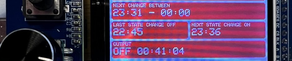
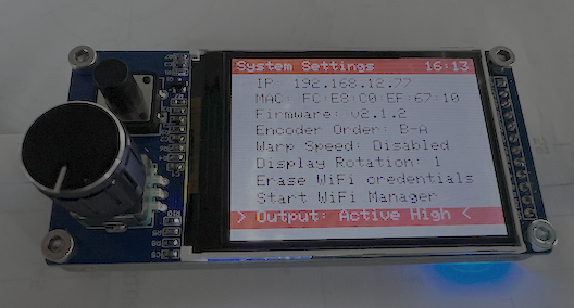
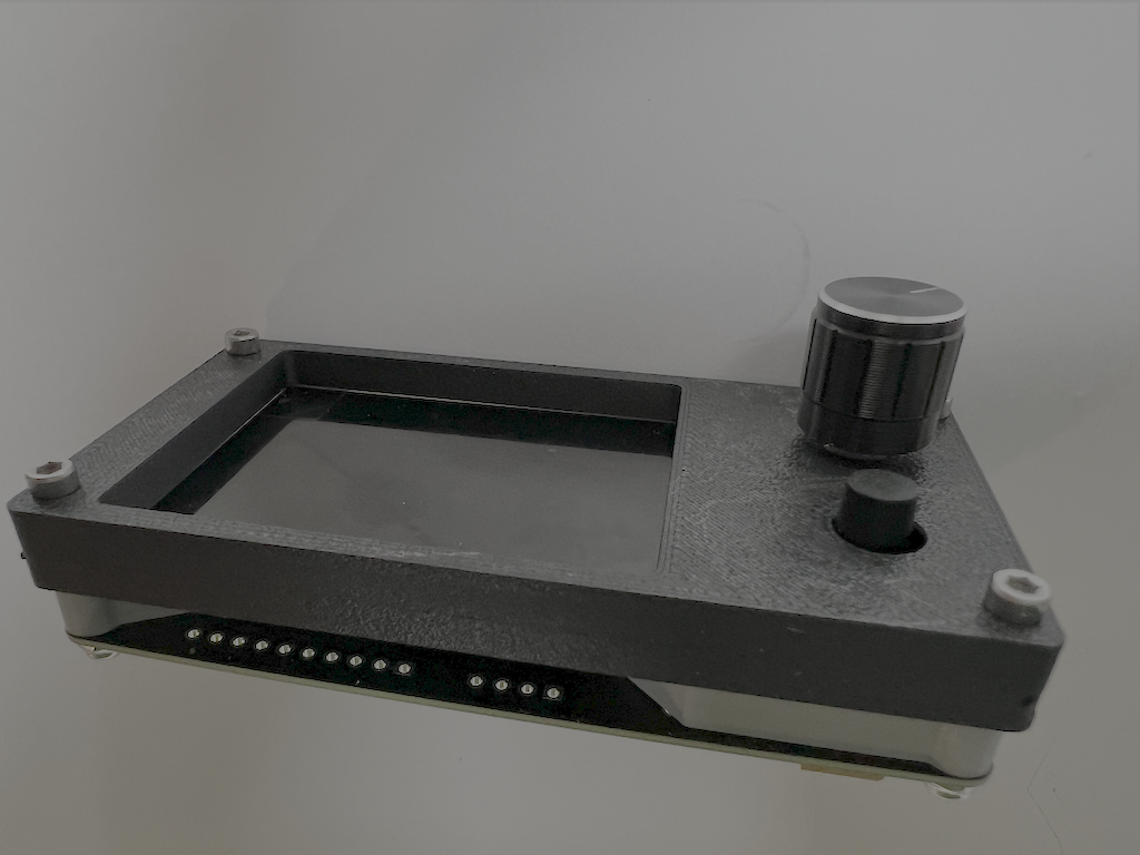
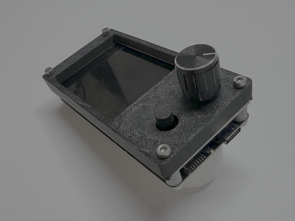
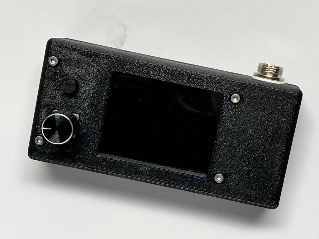
While browsing the internet, I came across this “TFT LCD Display EC11” board. It is a 2.4-inch color display with a rotary encoder and an extra push button. It’s a nice little board, but you need 12 connections to use the display, rotary encoder, and push button.
This project is sponsered by 
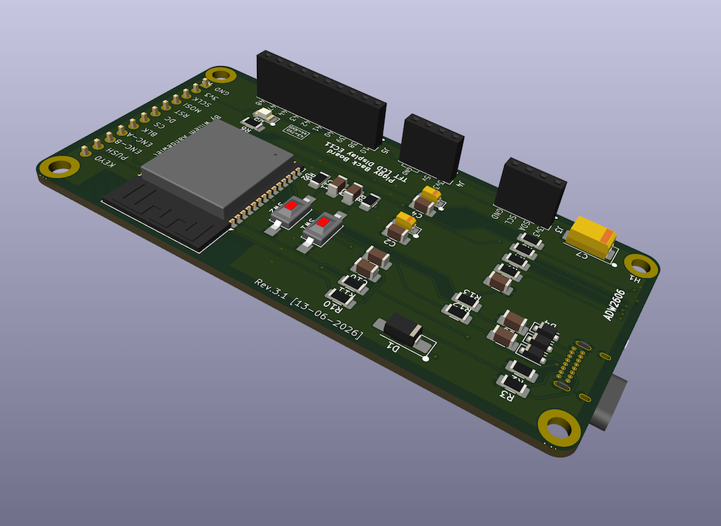
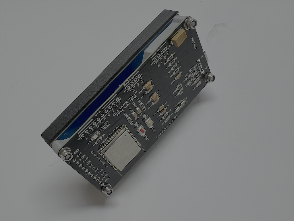
Inspired by the “Cheap Yellow Display” board that I used in an earlier project, I thought it would be interesting to design a piggy-back board for this display so it can be used in the same easy way as the Cheap Yellow Display.
This way, the maker only has to come up with a nice application and and write the software for it, without having to worry about all the hardware connections.
Possible applications could include:
- Internet Radio
- Universal Timer
- Smart Home Dashboard
- Drum Machine
- Audio Spectrum Analyzer
- Dashboard for ESPHome or Home Assistant
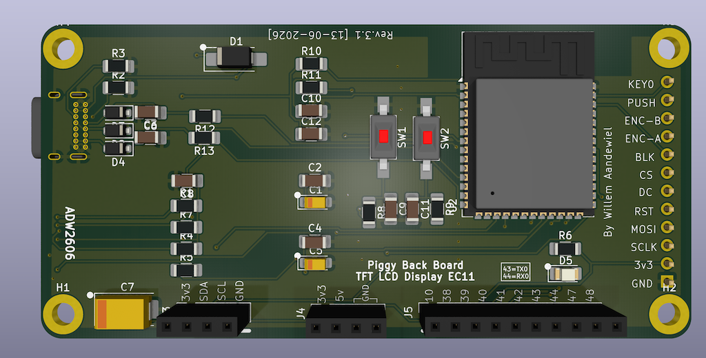
To connect external modules, such as sensors, the board features an I2C port with SDA (GPIO08), SCL (GPIO09), 3.3V, and GND, a universal connector with ten universal GPIO pins (GPIO10, GPIO38, GPIO39, GPIO40, GPIO41, GPIO42, GPIO43, GPIO44, GPIO47, and GPIO48), and a power port with 3.3V, 5V, and GND.
In an earlier version of such a piggyback board, I used an ESP32 with a CP2104 as a USB-to-UART bridge. In the current version (v3), I use an ESP32-S3 that has a built-in USB-to-UART bridge and also more free GPIO pins.
All of the components used are small, but easy to solder by hand.
Schematic
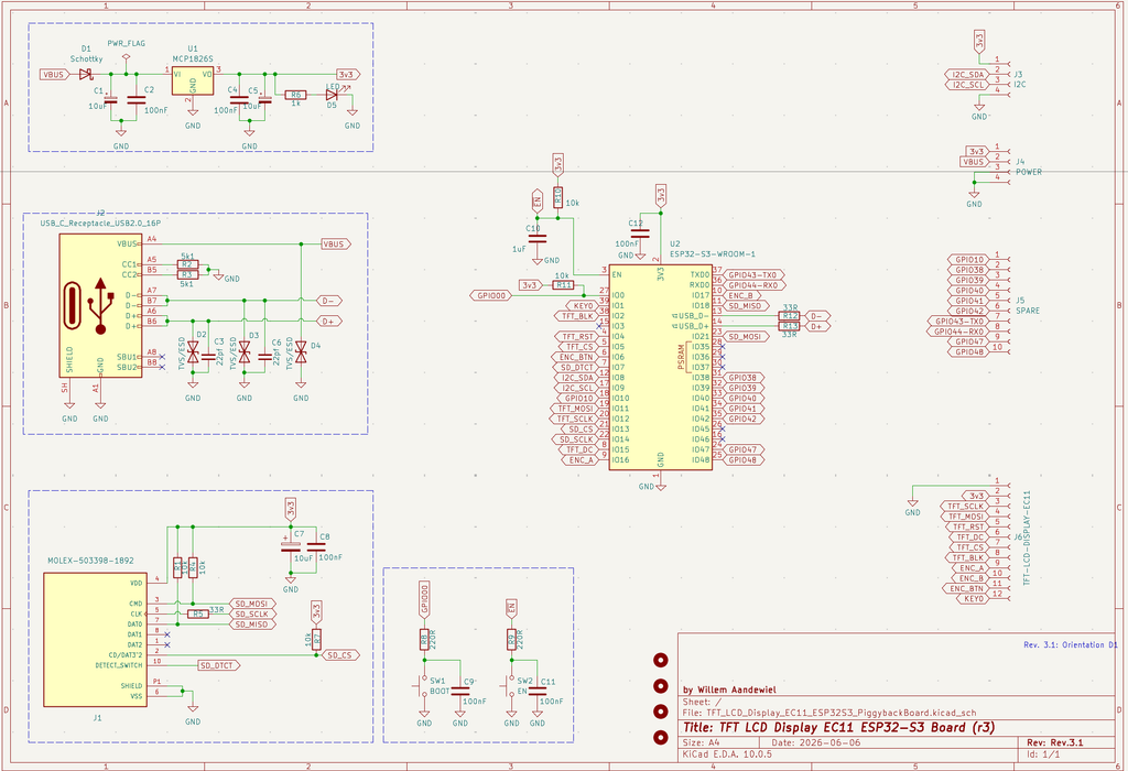
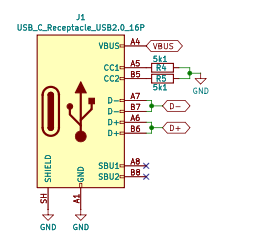
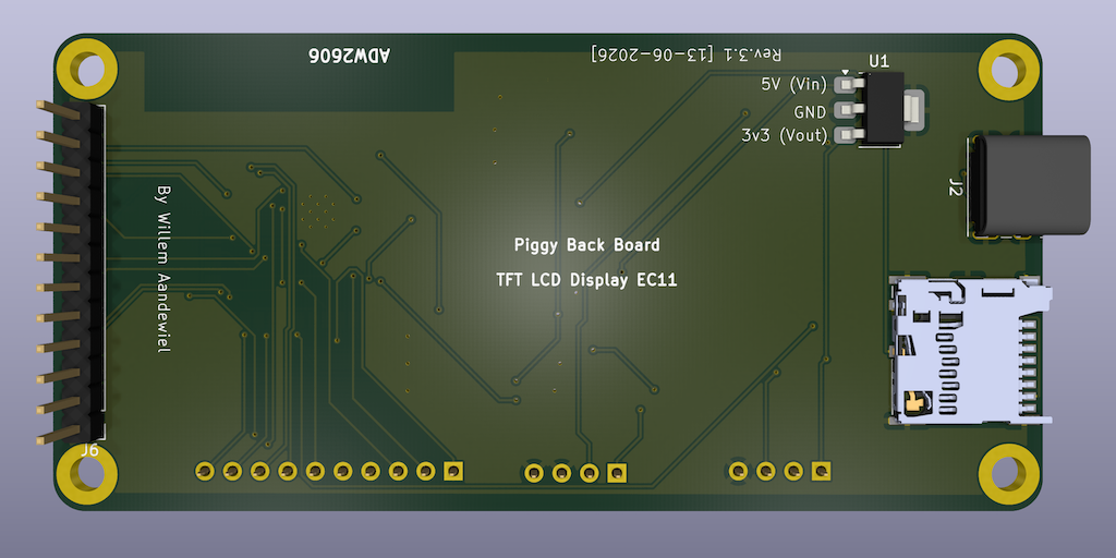
One difference from most of my other ESP8266 and ESP32 projects is that I chose to use a USB-to-UART bridge to program the SoC. Since USB-C has become the new standard, I decided to use this type as well. That is why the two 5k1 resistors (R2 and R3) are included. These are used to negotiate the required voltage with the USB hub or computer (in this case, 5 volts).
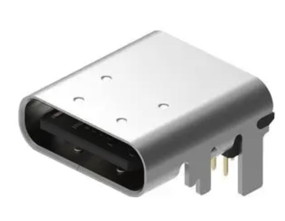
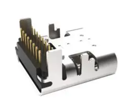
I selected a 16 pin Through Hole (THT) connector
(USB4085-GF-A)
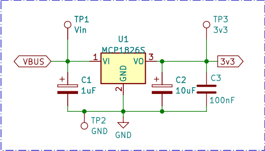
U1 is an MCP1826S (LDO) that can deliver up to 1 ampere. If you do not have one available, you can also use an LM2937-3.3V or a TC1262-3.3V. They have the same pinout, but provide a lower maximum current (500mA).
For ESD protection to protect the circuit against large voltage spikes, I use three TVS/ESD chips. Although it is sensible, it is not strictly necessary to solder the small components onto the PCB.
SW1 (and R8/C9) and SW2 (and R9/C11) are also not strictly necessary. If you mount them on the board, you can manually reset the SoC or put it into flash mode.
The esp32s3-piggyback board with display can be powered via the USB-C connector or via J4 (using the 5V pin!).
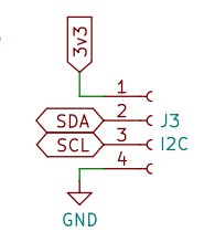
All connectors (J3, J4, and J5) have a pin pitch of 2.50mm. You can use any connector type you want. I prefer JST-XH connectors because they are relatively compact and the female connectors are easy to mount by hand. You can also use screw terminals or solder wires directly to the PCB.
The schematic is otherwise fairly straightforward.
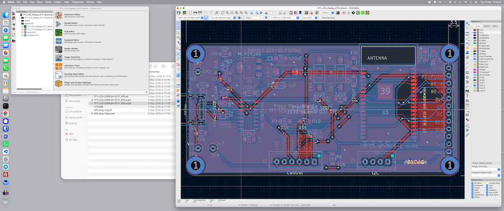
After designing the PCB in KiCad, I sent the design to for production.
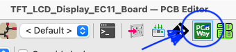
KiCad includes a very handy add-on that can automate the entire process with a single click.
I like working with because they really understand what makers need. Whenever I design a new ESP32 project, custom PCB, or hardware prototype, I mainly care about two things: high quality and fast delivery. And that’s exactly where stands out for me.
The quality of the PCBs has consistently been excellent. Crisp silkscreen printing, clean solder masks, and professionally finished boards — even for small prototype orders. That gives me confidence when I test new designs or share projects online.
What I value most personally is the speed. In many cases, I receive my PCBs within just a few days. That allows me to iterate faster, solve problems quickly, and continue building without long delays.
For my own projects, has become my go-to PCB manufacturer!
Before ordering the PCB, the only remaining choices are the PCB thickness, the PCB color, and the silkscreen color. Because the through-hole USB-C connector has very short pins, I chose a PCB thickness of 1mm instead of the standard 1.6mm.
Bill of Materials
| Reference | Value | Footprint | Comment |
|---|---|---|---|
| C2, C4, C8, C12 | 100nF | C_1206_3216Metric_Pad1.33×1.80mm_HandSolder | |
| (*) C9, C11 | 100nF | C_1206_3216Metric_Pad1.33×1.80mm_HandSolder | Not required |
| C1, C5 | 10uF | CP_EIA-3216-18_Kemet-A_HandSolder | |
| (*) C3, C6 | 22pf | C_1206_3216Metric_Pad1.33×1.80mm_HandSolder | Not required |
| C7 | 10uF | CP_EIA-7343-31_Kemet-D_HandSolder | |
| C10 | 1uF | C_1206_3216Metric_Pad1.33×1.80mm_HandSolder | |
| R1, R4, R7, R10, R11 | 10k | R_1206_3216Metric_Pad1.30×1.75mm_HandSolder | |
| R5, R12, R13 | 33R | R_1206_3216Metric_Pad1.30×1.75mm_HandSolder | |
| R2, R3 | 5k1 | R_1206_3216Metric_Pad1.30×1.75mm_HandSolder | |
| (*) R8, R9 | 220R | R_1206_3216Metric_Pad1.30×1.75mm_HandSolder | Not required |
| R6 | 1k | R_1206_3216Metric_Pad1.30×1.75mm_HandSolder | |
| (*) D2, D3, D4 | TVS/ESD | D_SOD-123F | Not required |
| D1 | Schottky | D_SMA_Handsoldering | |
| D5 | 3v3 | LED_1206_3216Metric_Pad1.42×1.75mm_HandSolder | |
| U1 | MCP1826S | SOT-223-3_TabPin2 | |
| U2 | ESP32-S3-WROOM-1 | ESP32-S3-WROOM-1 | |
| (*) SW1 | BOOT | SW_SPST_FSMSM | Not required |
| (*) SW2 | RESET | SW_SPST_FSMSM | Not required |
| J1 | MOLEX-503398-1892 | MOLEX_503398-1892_mod | |
| J2 | USB_C_Receptacle_USB2.0_16P | USB_C_Receptacle_GCT_USB4085 | |
| J3 | I2C | PinSocket_1x04_P2.54mm_Vertical | |
| J4 | POWER | PinSocket_1x04_P2.54mm_Vertical | |
| J5 | SPARE | PinSocket_1x10_P2.54mm_Vertical |
GPIO Pins Used
Important — Strapping pins
The ESP32-S3 Piggyback Board does not expose any of the ESP32-S3 strapping pins.
Pins Used by the Board
- GPIO00 – PIN_BOOT
- GPIO01 – PIN_TFT_KEY0
- GPIO02 – PIN_TFT_BLK
- GPIO04 – PIN_TFT_RST
- GPIO05 – PIN_TFT_CS
- GPIO06 – PIN_TFT_ENC_BTN
- GPIO07 – PIN_SD_DTCT
- GPIO08 – PIN_I2C_SDA
- GPIO09 – PIN_I2C_SCL
- GPIO11 – PIN_TFT_MOSI
- GPIO12 – PIN_TFT_SCLK
- GPIO13 – PIN_SD_CS
- GPIO14 – PIN_SD_SCLK
- GPIO15 – PIN_TFT_DC
- GPIO16 – PIN_TFT_ENC_A
- GPIO17 – PIN_TFT_ENC_B
- GPIO18 – PIN_SD_MISO
- GPIO21 – PIN_SD_MOSI
Pins routed to the outside via J5
- GPIO10 – SPARE
- GPIO38 – SPARE
- GPIO39 – SPARE
- GPIO40 – SPARE
- GPIO41 – SPARE
- GPIO42 – SPARE
- GPIO43 – SPARE / TX0
- GPIO44 – SPARE / RX0
- GPIO47 – SPARE
- GPIO48 – SPARE
 Follow