Introducing the Universal Prototyping Board
3,518 keer bekeken / views
In the intricate world of microcontroller unit (MCU) development, versatility is often sacrificed for specificity. However, imagine a single solution that transcends these limitations – the Universal Prototyping Board.
Unlike its predecessors I designed …
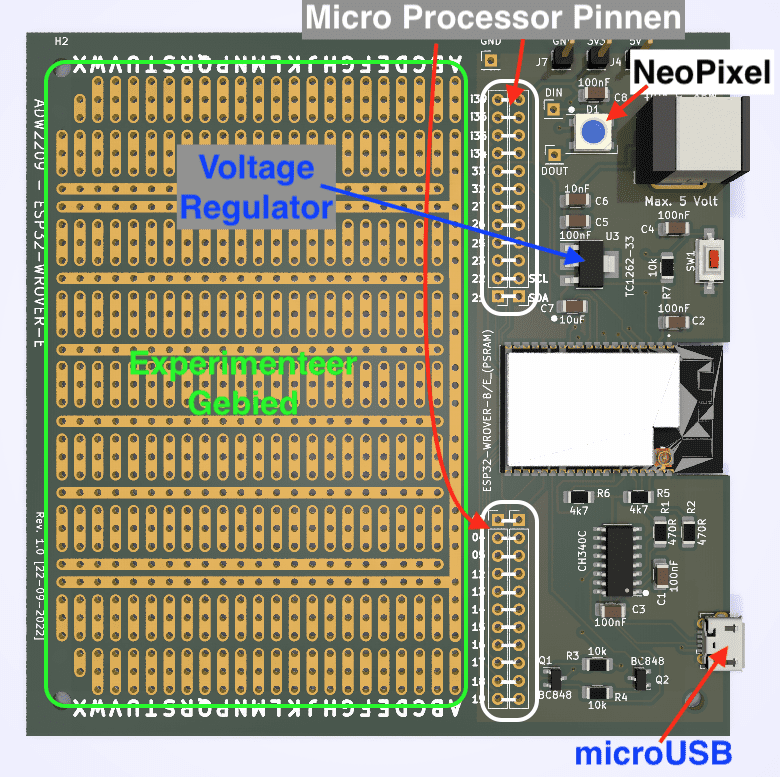
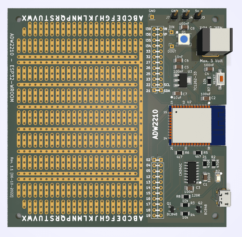
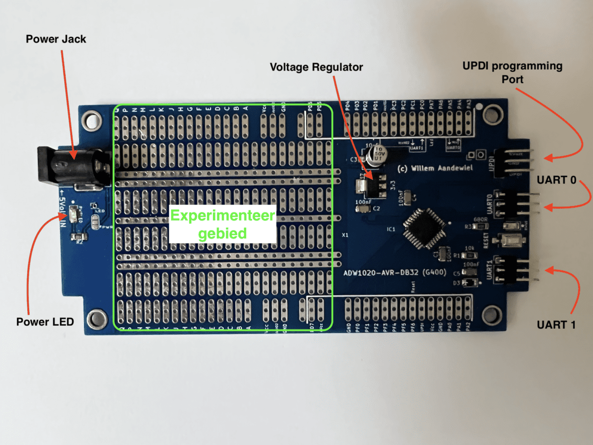
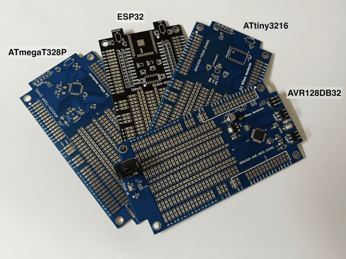
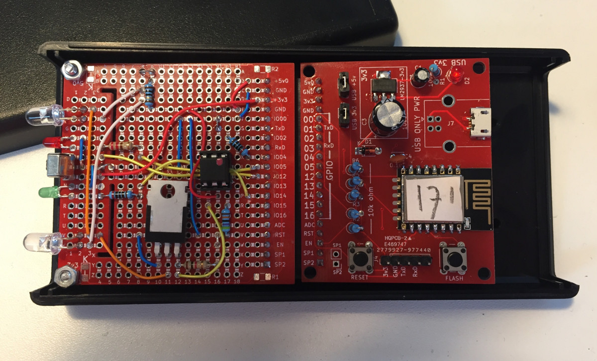
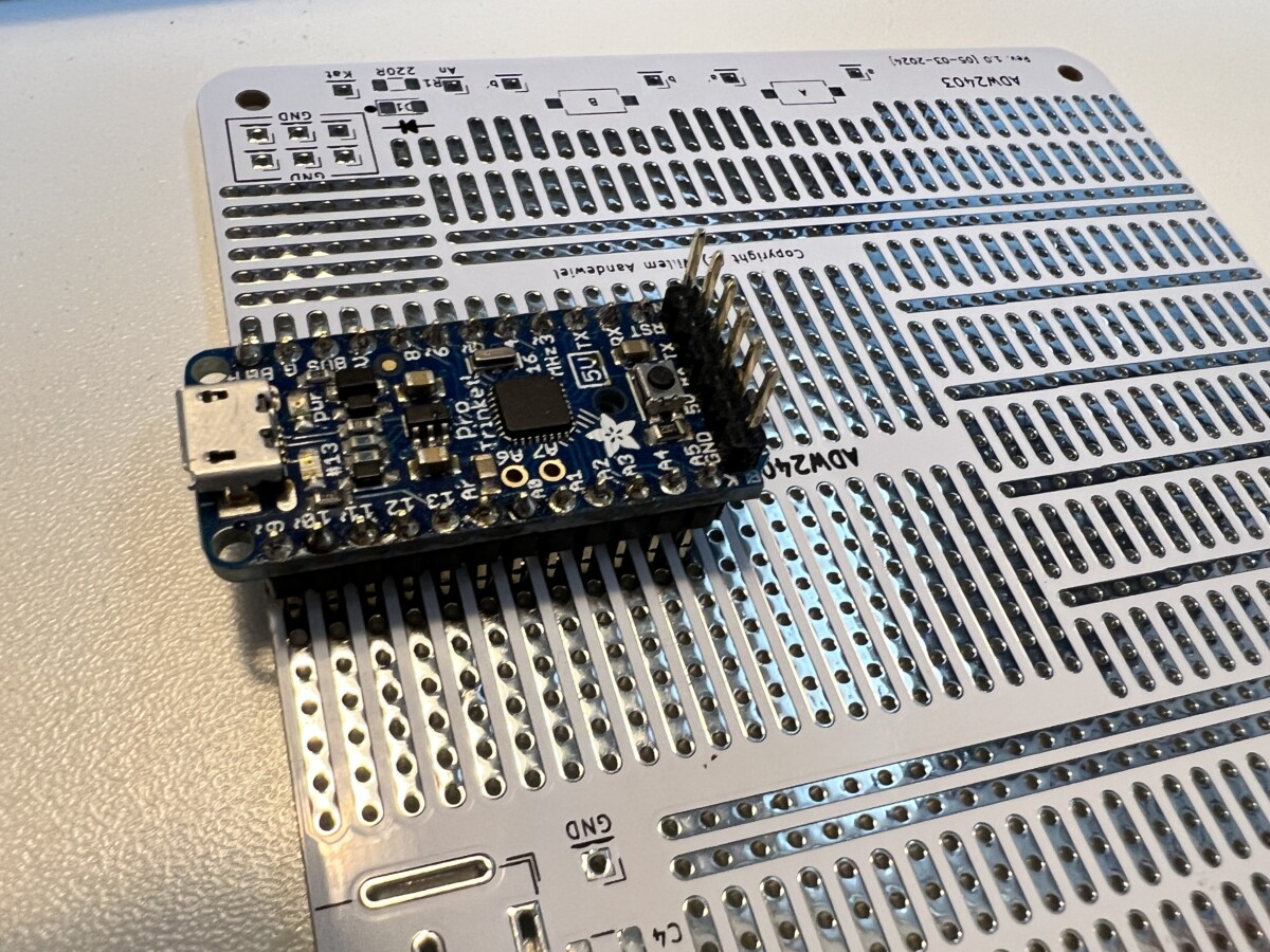
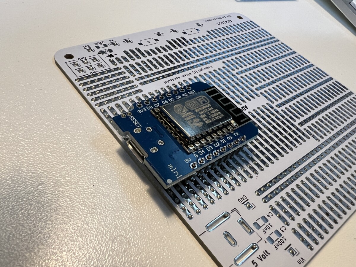
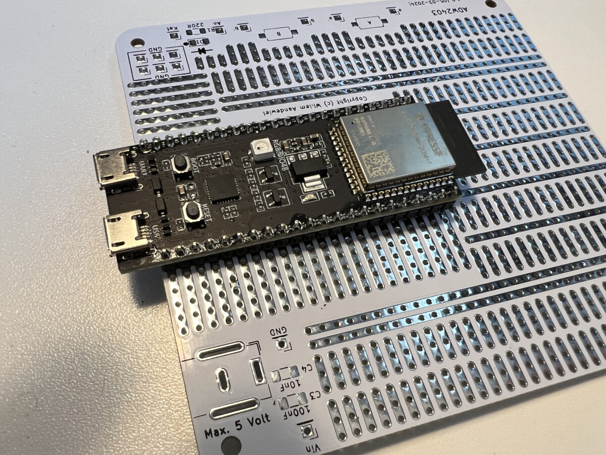
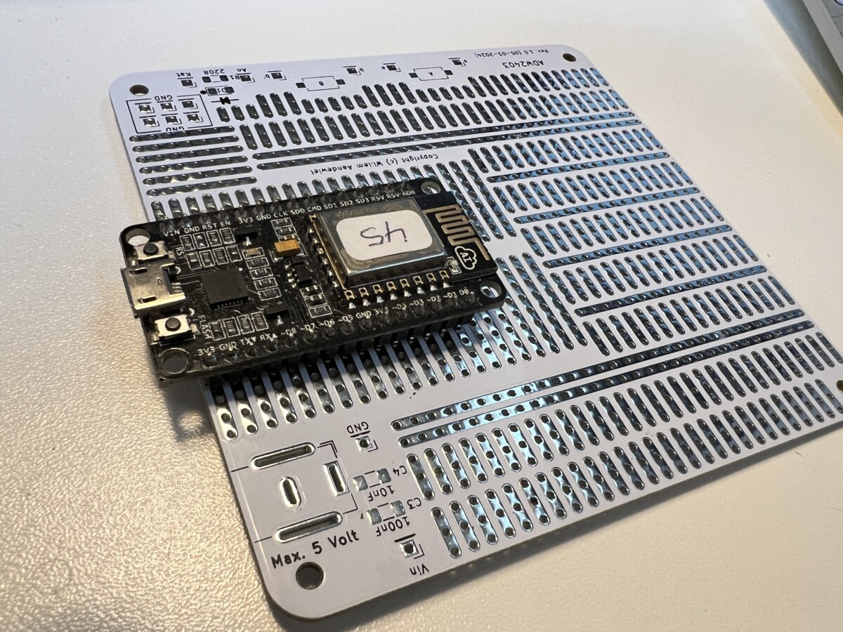
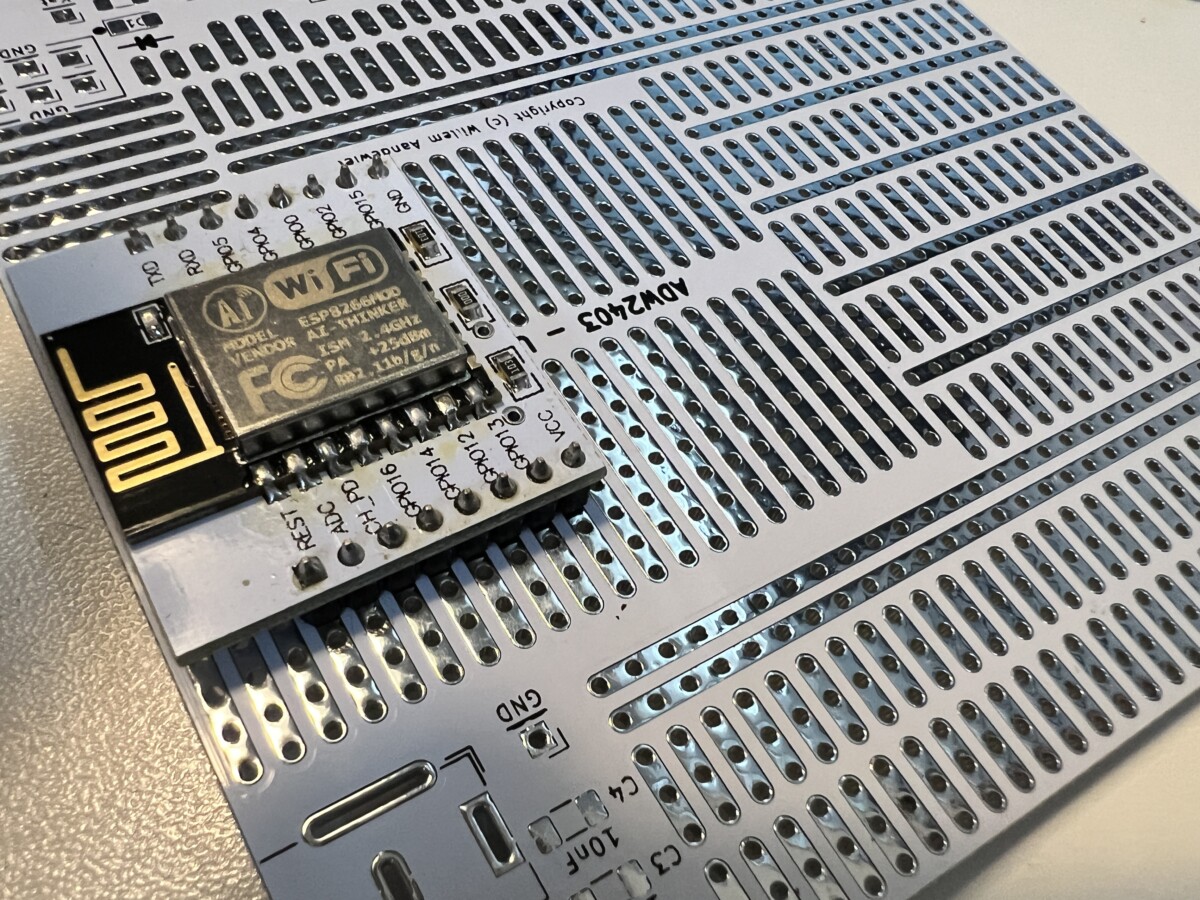
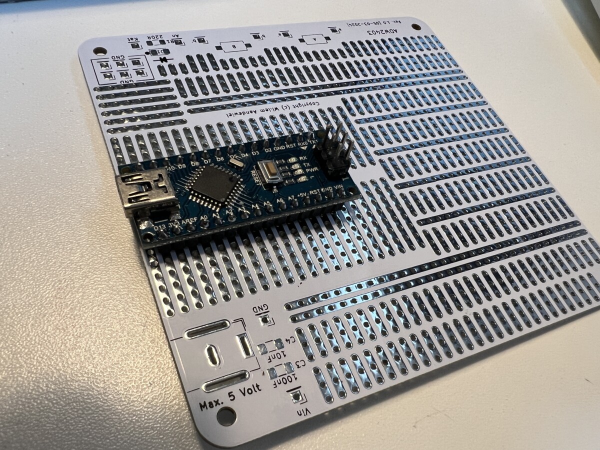
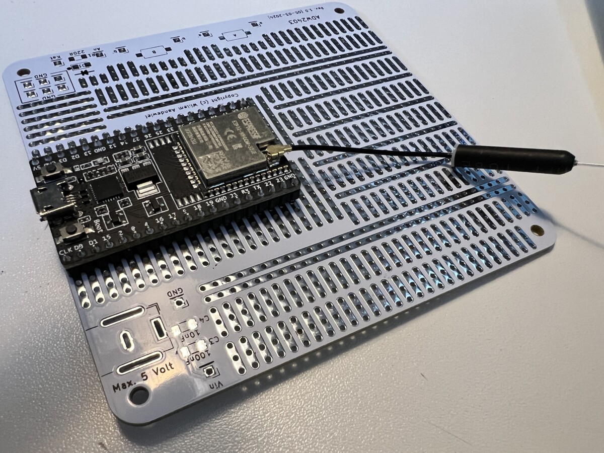
… which were tailored for specific MCU types. This restricted the flexibility and I had to make different boards for different projects. The Universal Prototyping Board changes this by offering a singular platform capable of accommodating various MCU models. From the ESP8266 and ESP32 to Arduino Nano, STM32 Nucleo-32, Teensy, Raspberry Pi Pico, and even microprocessors in DIN format (Atmel, now Microchip), this board opens doors to endless possibilities.
Adaptability Unleashed
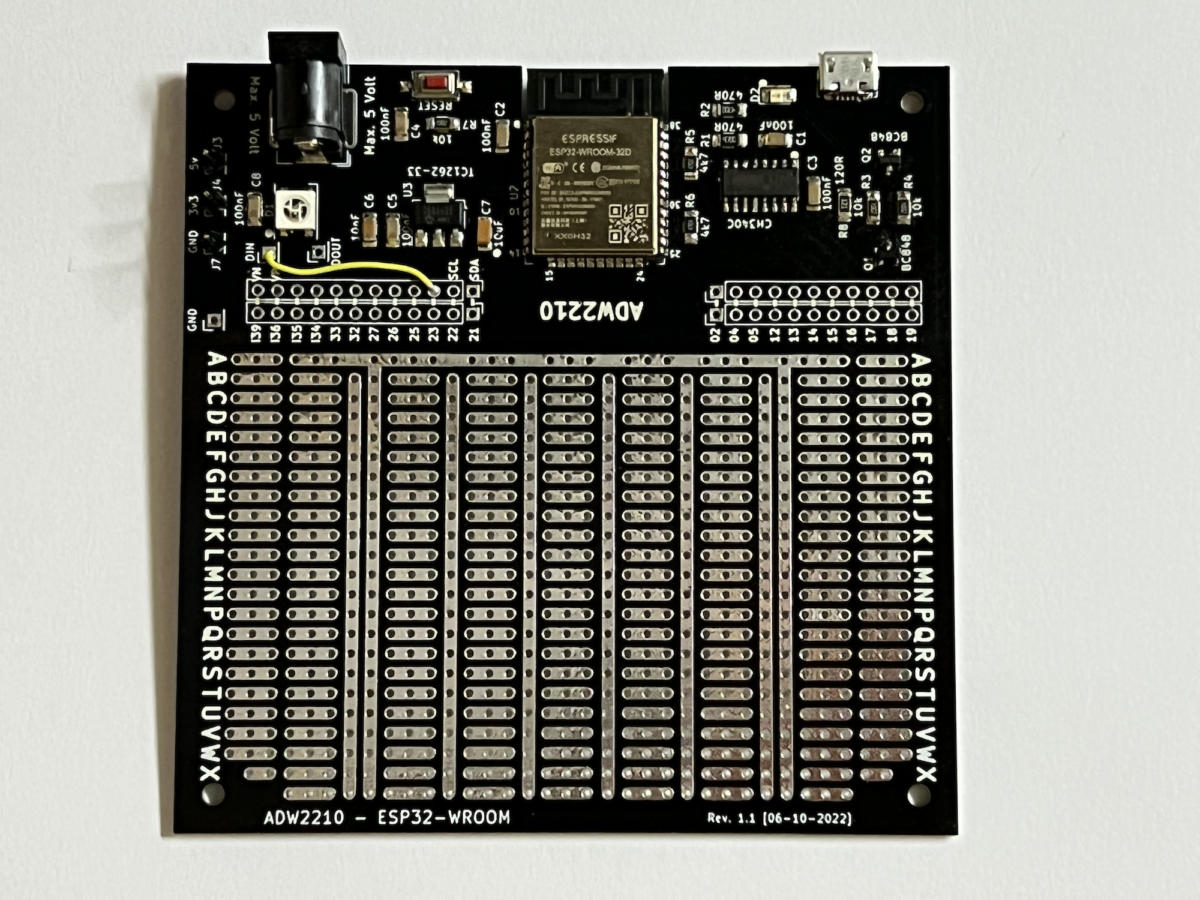
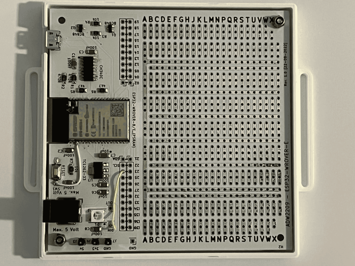
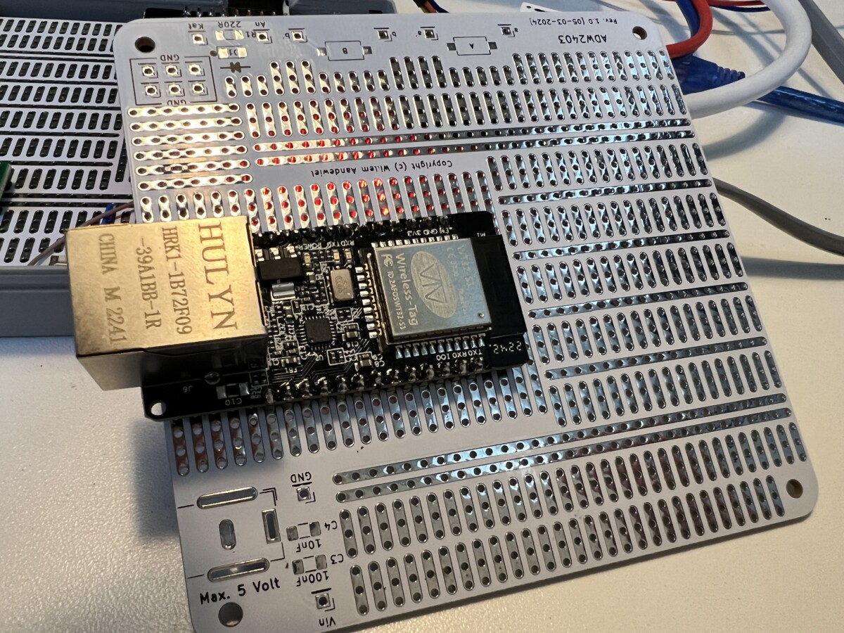
With its universal design, the Universal Prototyping Board empowers developers to adapt and experiment like never before. The 35×18 to 35×25 (and then some) standard breadboard holes provide a spacious canvas for prototyping, allowing users to explore different configurations and connections effortlessly. Whether you’re a hobbyist tinkering with a personal project or a professional engineer working on a commercial venture, this board adapts to your needs, offering unrivalled versatility at every turn.
Simplified Development Process
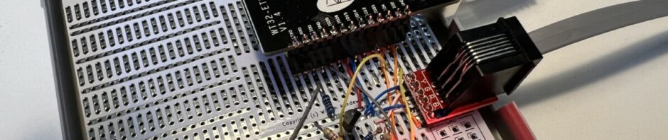
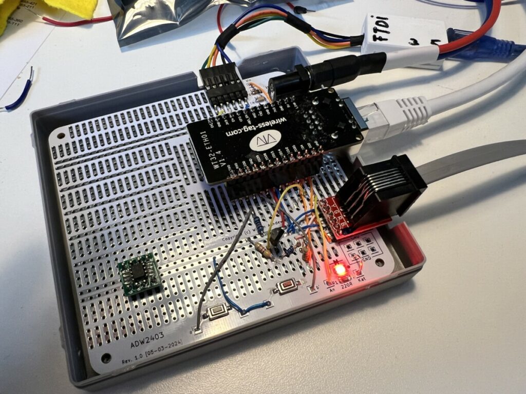
Gone are the days of grappling with compatibility issues and struggling to find the right prototyping board for your project. The Universal Prototyping Board streamlines the development process, enabling seamless integration with a diverse range of peripherals and components. With its intuitive layout and straightforward design, getting started is a breeze – simply solder in your chosen MCU board (or use pin headers to plug it in), solder and connect your components, and start testing.
Future-Proof Design
In an ever-evolving landscape, adaptability is essential. The Universal Prototyping Board is built to evolve alongside your projects, ensuring that you’re always equipped to tackle new challenges and embrace emerging technologies. Whether you’re experimenting with cutting-edge sensors, exploring advanced communication protocols, or integrating AI capabilities, this board provides the flexibility and scalability you need to stay ahead of the curve.
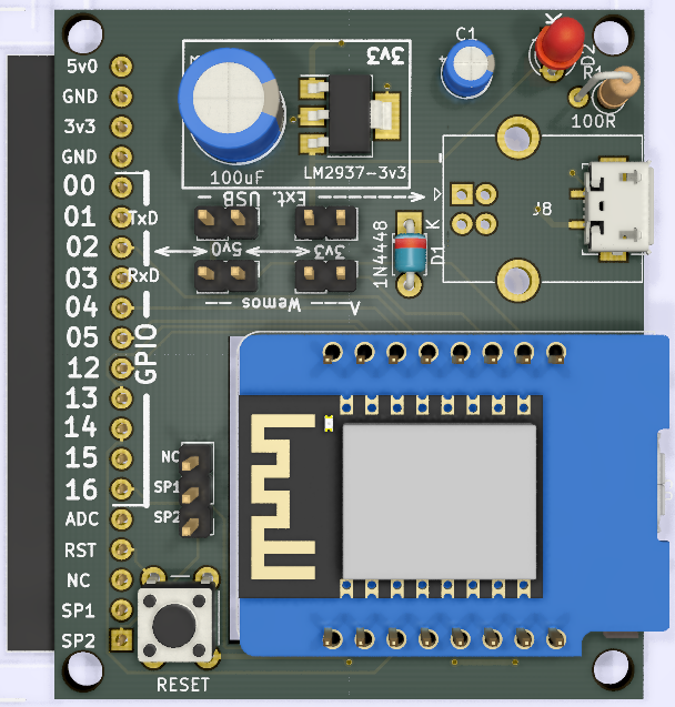
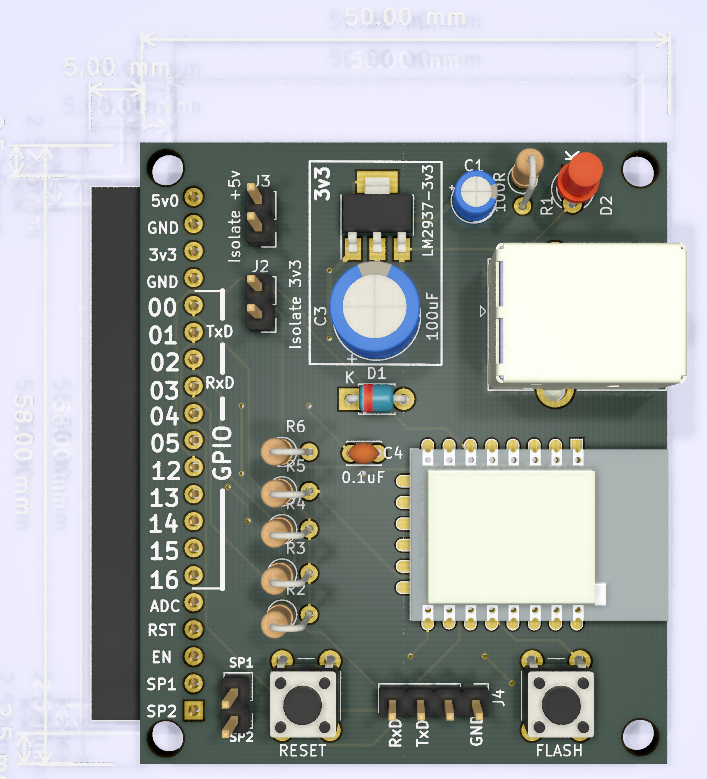
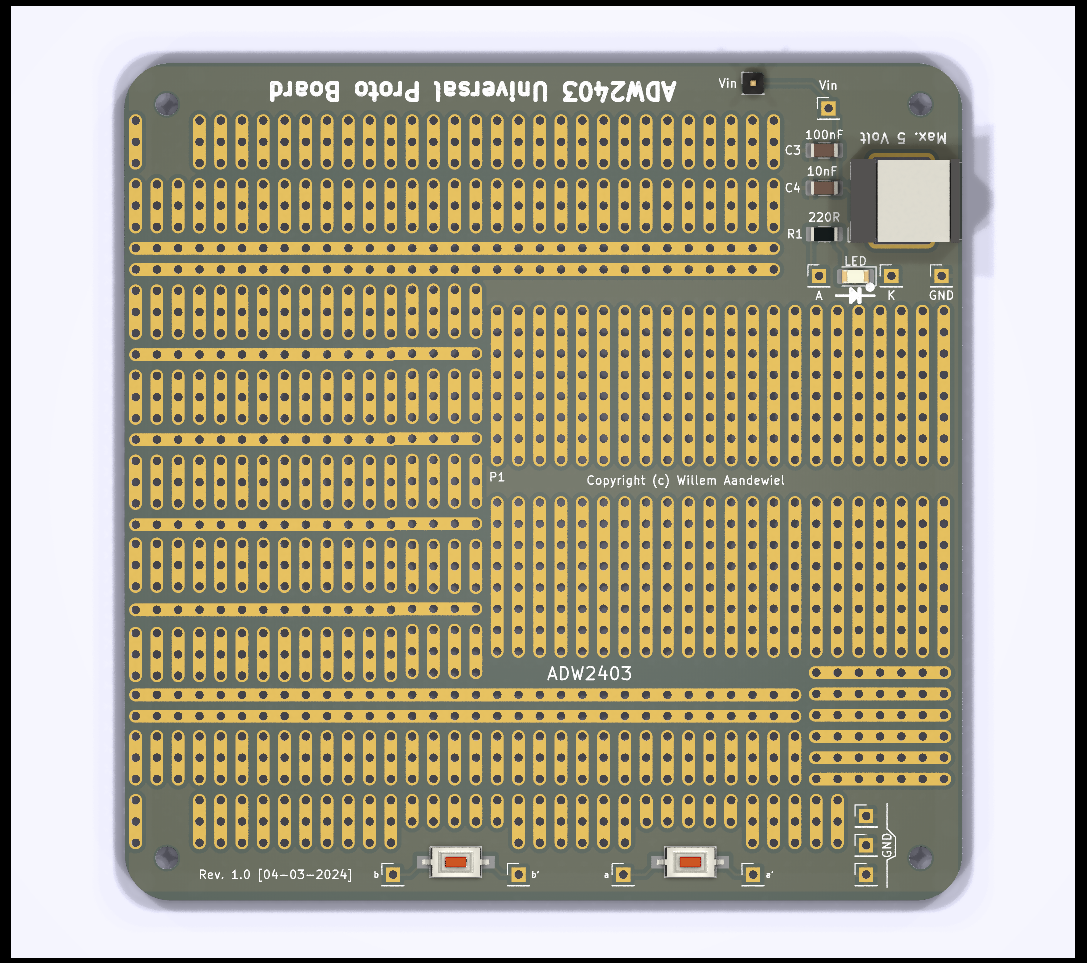
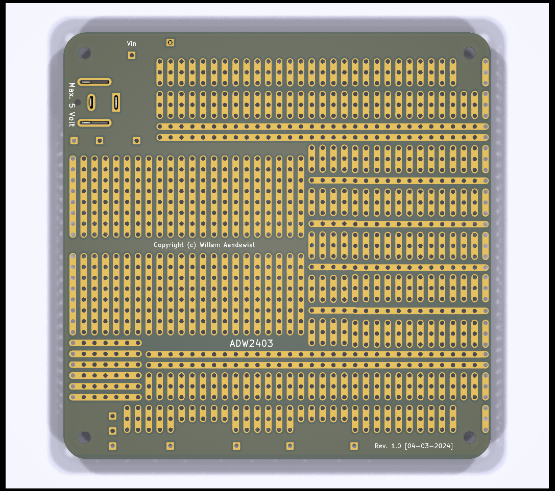
The Printer Circuit Board
I use KiCad (7.x) for designing the PCB.
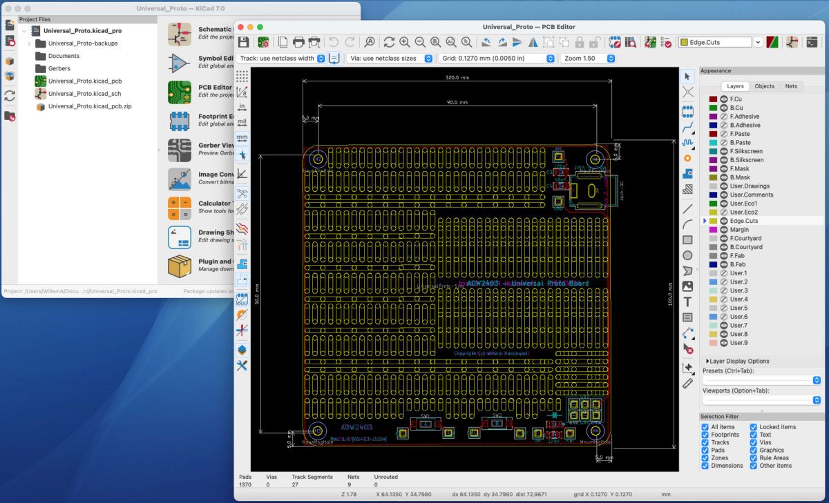
After the printed circuit board has been designed, the design (in the form of Gerben files) must …
… be sent to a PCB manufacturer. I like to use ![]() .
.
PCBWay prides itself on delivering high-quality PCBs crafted with precision and attention to detail. Utilizing state-of-the-art manufacturing processes and cutting-edge equipment, PCBWay ensures that every board meets rigorous quality standards. Whether you’re prototyping a new project or mass-producing a commercial product, you can trust PCBWay to deliver PCBs that meet your exact specifications and performance requirements.
In today’s fast-paced world, time is of the essence. PCBWay understands the importance of quick turnaround times and offers expedited manufacturing and delivery options to meet tight deadlines. With efficient production processes and streamlined logistics, PCBWay can produce and ship PCBs in record time, allowing you to move forward with your projects without delay.
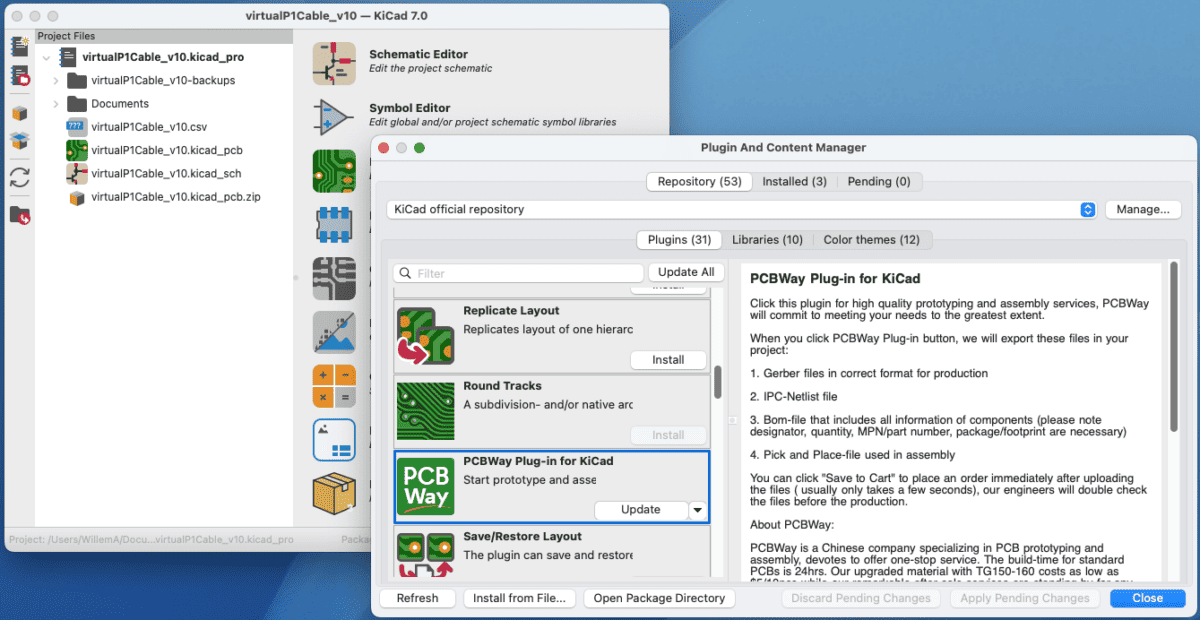
KiCad has a nice plugin that can automate the process of sending the correct files in the correct format to PCBWay. The plugin is called “PCBWay” (how did they come up with that). Installation is done via KiCad’s “Plugin and Content Manager”.
After installation, the KiCad toolbar has a new button.
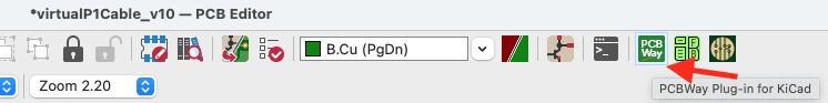
By clicking this button, all files required for PCBWay are placed in a .zip file and you jump to the PCBWay website via the browser.
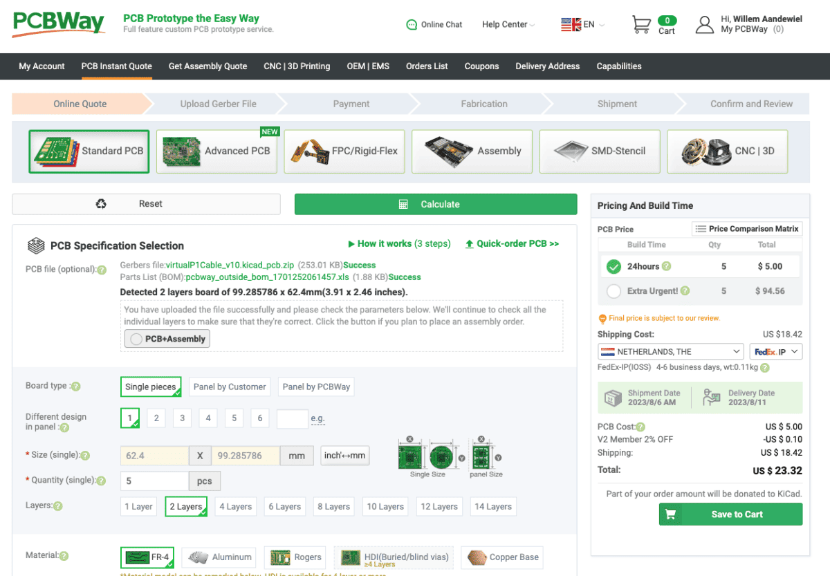
You then indicate how many printed circuit boards you want to have made of this design and what you want the printed circuit board to look like (color of the solder mask and silk screen).
After inspection by the engineers of ![]() you can pay the production and shipping costs. After about a week, your printed circuit boards will be delivered and you will find them in your mailbox!
you can pay the production and shipping costs. After about a week, your printed circuit boards will be delivered and you will find them in your mailbox!
Wrapping it up
If you want to you can now solder the switches, led and Power Jack on the board. They are not necessary but in most projects you need one ore more switches and sometimes a LED is ‘nice to have‘. You can also add the 5mm Power Jack (if your MCU board does not have a USB connector that can provide the power).
 Follow