[ 4,455 keer bekeken / views ]
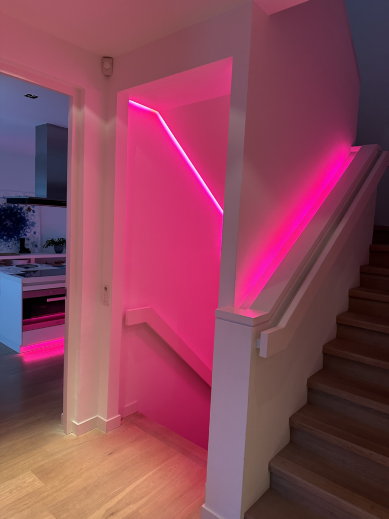
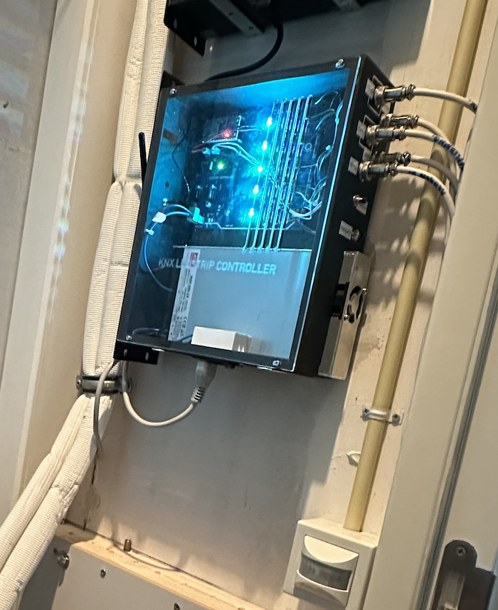
When a friend of my bought his house a few years ago it was mostly wired with KNX. Later “improvements” where done by contractors who did not know the beauty of KNX. So by the time he bought this house there now was a mix of KNX and other systems installed under which nine RGB LED strips spread around the house. The RGB LED strips are controlled by nine beefy controllers that each control one LED strip.
Every LED strip controller has its own 24 volt power supply and the colours of the nine strips are, in turn, controlled by one “one channel” controller box located and operated in an utility closed. So all the strips show the same colour and intensity.
This is far from optimal if only for the large space (an other full utility closet) the controllers occupy
So he asked me to design something better (individual colours and intensity for each LED strip) in lesser space. As my friend is a software engineer himself, he will take care of the software for the ESP32 to control each and every RGB LED strip by the KNX protocol.
If KNX is not needed it is not that difficult to write a webserver for the ESP32 to control the RGB LED strips.
Design Choices
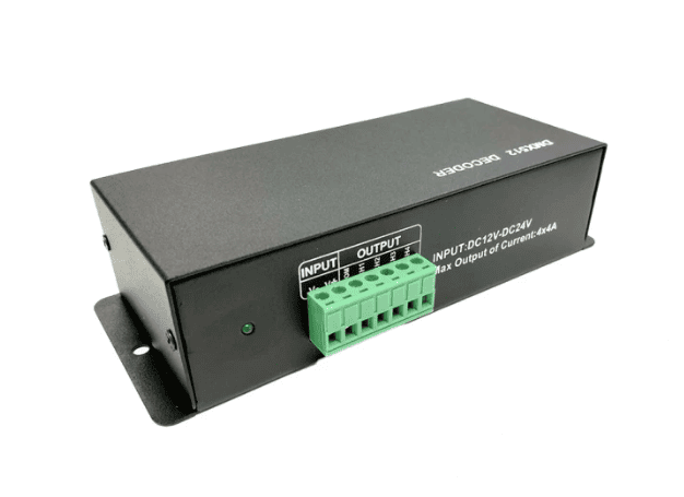
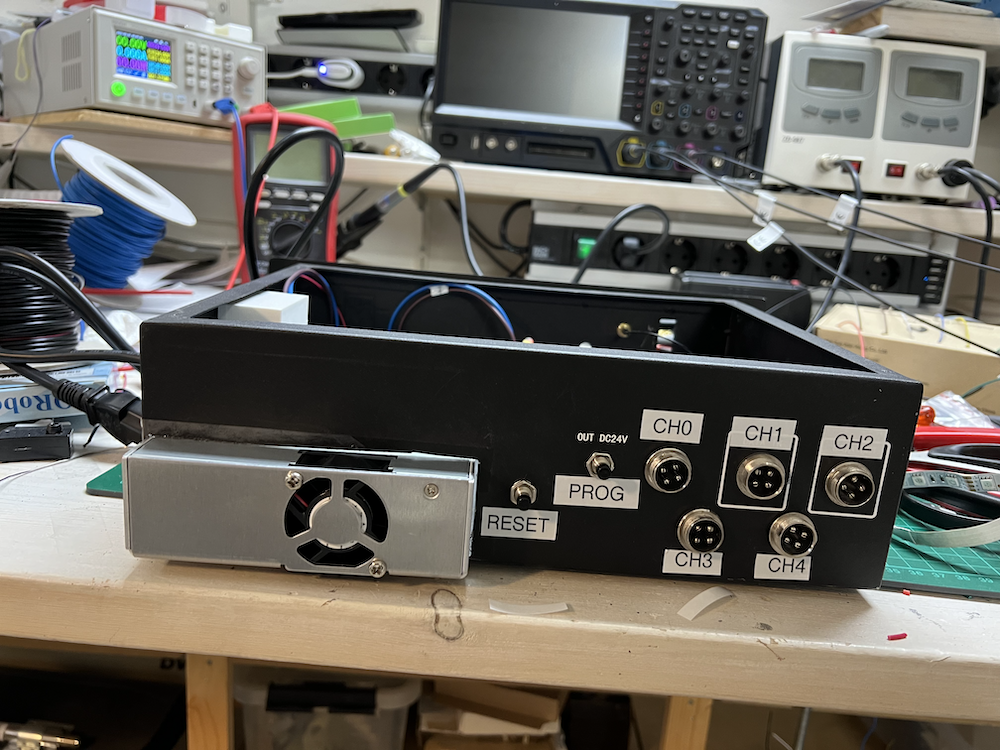
To pursue circular design we want to re-use the casing, the wiring and the connectors (4-pole DIN) of the current controllers.
For controlling the RGB LED strips the obvious choice is to use Power Mosfets to switch the individual LED colours in the strips and Pulse Wide Modulation (PWM) to control the intensity.
Mosfets are great devices that can switch large currents by applying a voltage between the gate and the source.
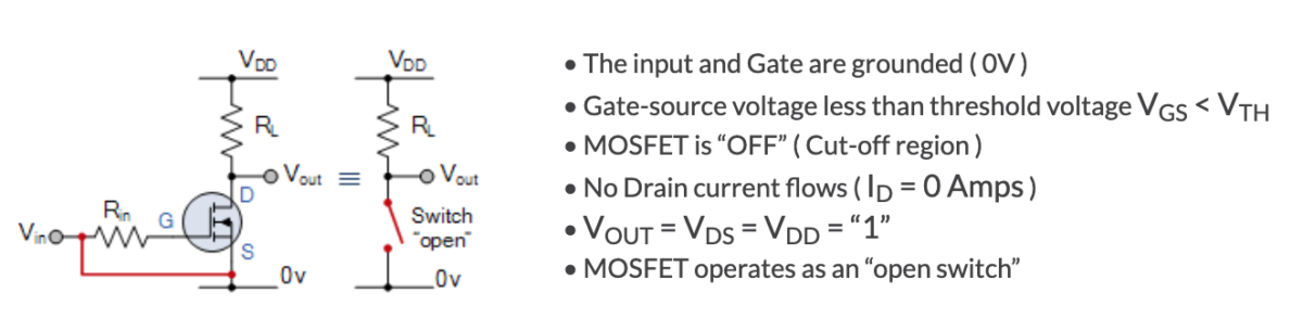
But there is a pitfall!
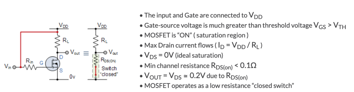
A Mosfet is, basically, a variable resistor that has a value of, almost, zero ohms to, almost, infinite ohms. At those two extremes the power dissipation of the Mosfet is almost zero and the Mosfet will not convert energy into heath. Which is great.
But the problem is in the range between the two extremes. If you don’t switch the Mosfet fast enough between ~zero ohm (closed) and ~infinite ohm (open) there will be a lot of energy dissipated and the Mosfet can get very hot!
What most people do not realise is that the gate-source and gate-drain junction have a (relative) large capacitance.
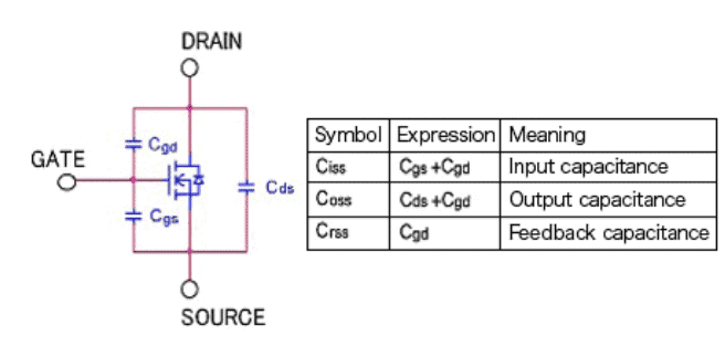
If you pull the gate to GND there will be a large discharge current flowing “out of” the gate (up to several amps). If you connect the gate to Vdd again a large current will flow between Vdd to the gate to charge the gate (also up to several amps).
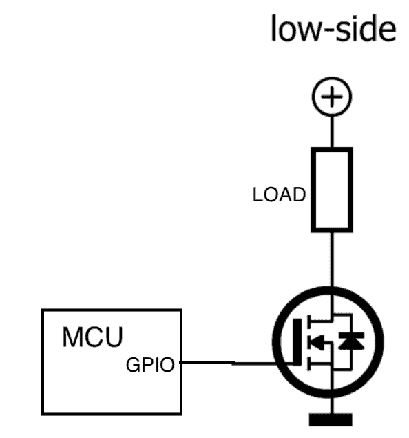
So what will happen if you connect the gate to a GPIO pin of a micro processor that can drive about 20mA?
Well: the GPIO pin will cease to be (free from Monty Python)!
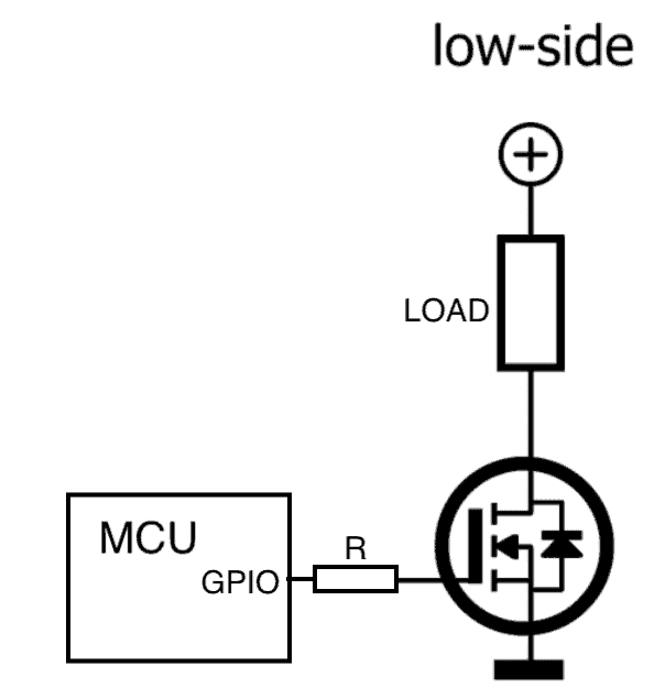
The solution most designs use to prevent this is a series resistor (R) between the GPIO pin and the gate.
Problem solved … or not.
The series resistor prevents the GPIO pin from blowing up by limiting the current but it also makes the gate switch time (R/C time) longer and the Mosfet will spent more time in the transition between open and closed (and vice versa) and thus will create more heat.
Totem Pole driver circuit
One way to solve this is by making use of a so called “Totem Pole” circuit that is capable of driving a large current to switch the gate of the Mosfet.
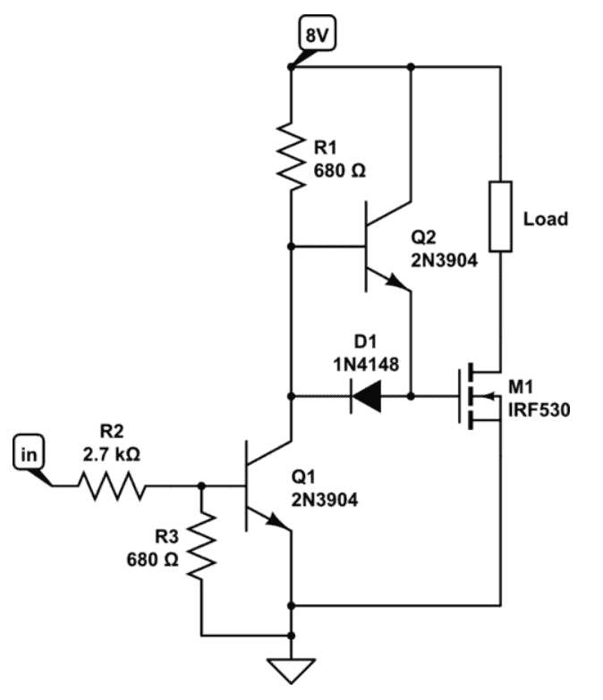
But this circuit takes a lot of parts and is rather complex.
UCC2742 Driver IC
And then the Mosfet Driver IC’s come to rescue! These IC’s are capable of charging and discharging the gate capacitance with a large current (up to 4 amps) and limiting the transition time of the Mosfet, and the power dissipation to a minimum.
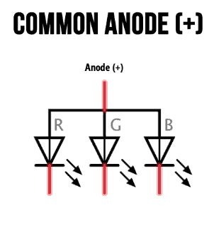
Be aware that the circuit is designed for Common Anode type LED strips!
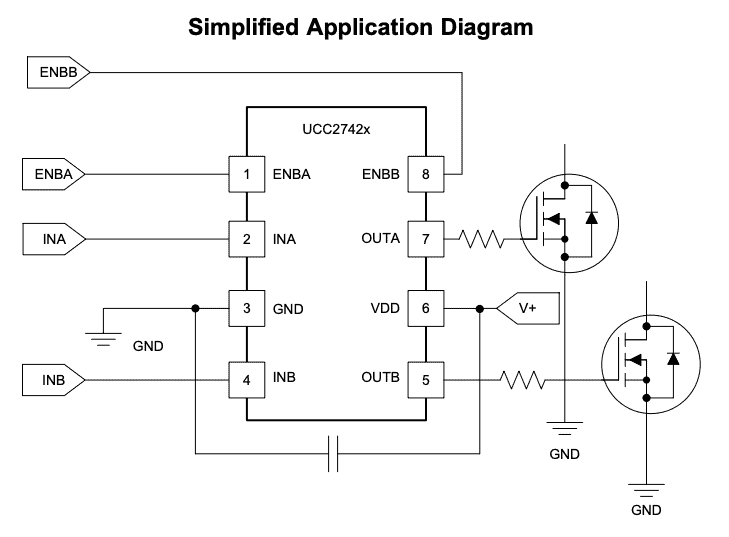
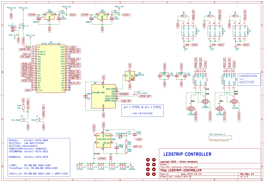
The driving circuit for the LED strip controller looks like this:
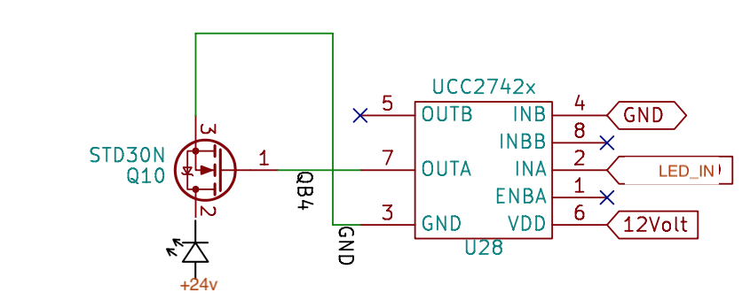
The UCC2742 (or FAN3224TMX) chip has two drivers (A and B). The enable pins ([ENBA] and [ENBB]) are internally pulled high.
To control one RGB LED strip we need three of these driver circuits. The MCU of choice is the ESP32-DevKitC which have 32 GPIO pins from which 22 are at our disposal (but four of them are input only pins). We also need some control signals therefore we can control a maximum of five LED strips (15 GPIO pins).
BCR420 LED Driver
To give some feedback there are three coloured LED’s for each channel. There are many ways to connect a LED to a MCU. Most used is a series resistor to limit the current but I have chosen a so called “LED Driver” IC.
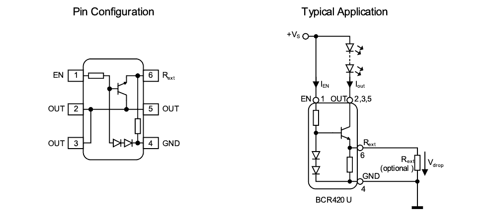
This small device limits the current through the LED by one resistor (Rext) over a wide range of voltages. Omitting the Rext will drive the LED with a current of 20mA.
ACS712
For a device capable of working with large currents it is always nice to have some information about the actual current the device is using and therefore an ACS712/ACS723 is incorporated in the circuit.
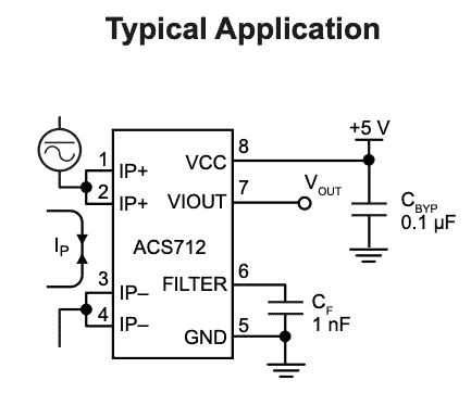
I use a -20 to +20 amp version (mainly because the 0 to +20amp versions are difficult to source).
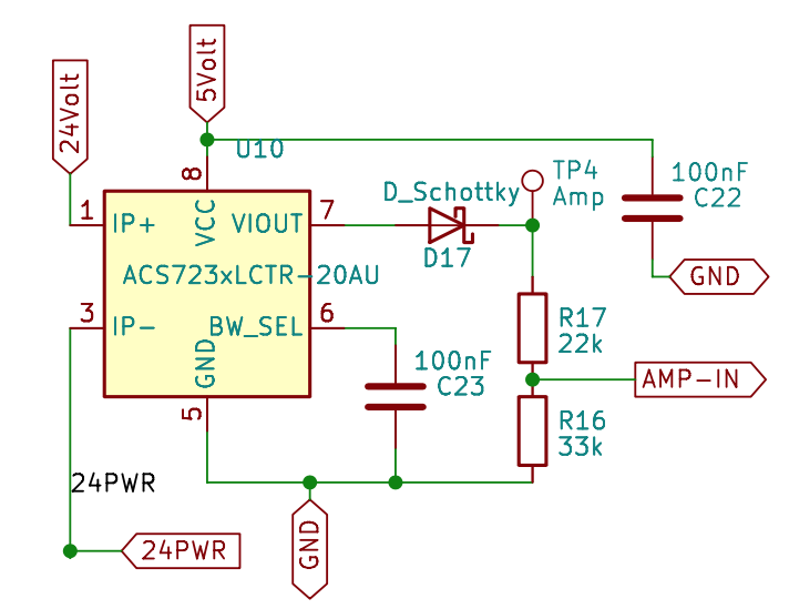
To limit the VIout voltage there is a resistor divider (R16/R17) that limits the 0-5 volt of the ACS712 to 0-3 volt that can be handled by the ADC of the ESP32.
External Watchdog
An external watchdog is also part of the design.
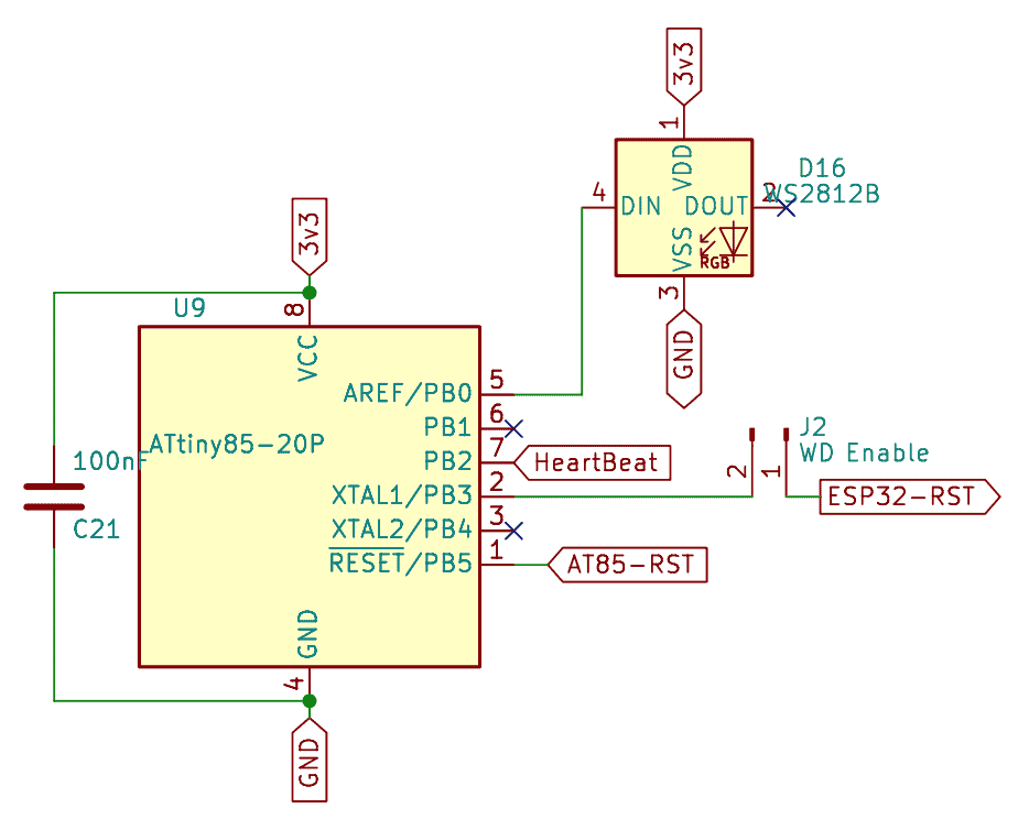
The watchdog is based on a ATtiny85 MCU that receives heartbeats from the ESP32 on PB2 (pin 7) and if the ESP32 crashes or otherwise stops sending heartbeats the ATtiny85 will reset the ESP32 by pulling PB3 (pin 2) HIGH. With a jumper on J2 the watchdog can be en- or disabled.
The ESP32 can reset the watchdog to its initial state by pulling PB5 HIGH.
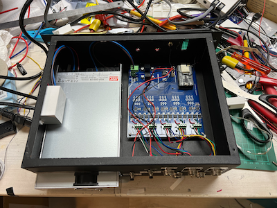
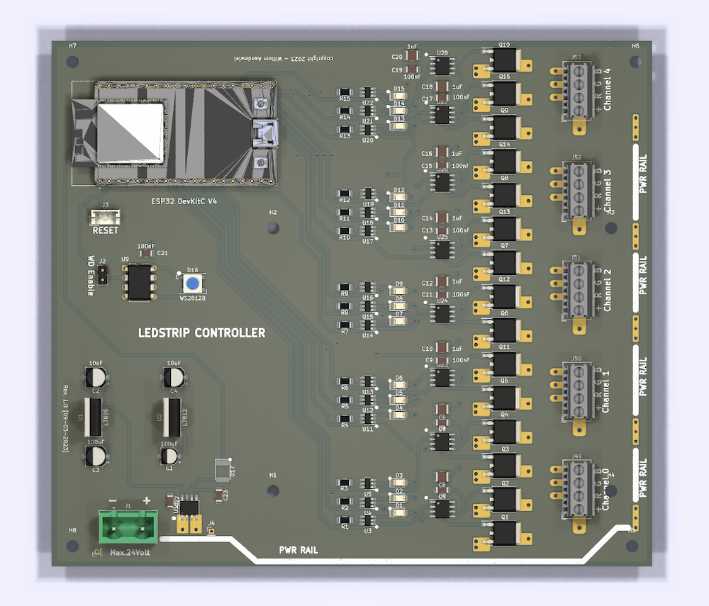
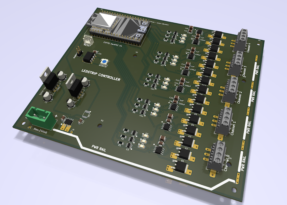
PCB Design
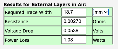
As the currents through the Mosfets and LED strips are large (up to 2 amps per colour and up to 20 amps -limited by the power supply- for power lines) a simple copper trace has to be 20mm wide to accommodate these large currents.
This would make the PCB very large so I have opted for smaller traces and solder a wire over them.
The complete schematic:
I send the design to PCBWay to produce the printed circuit board.
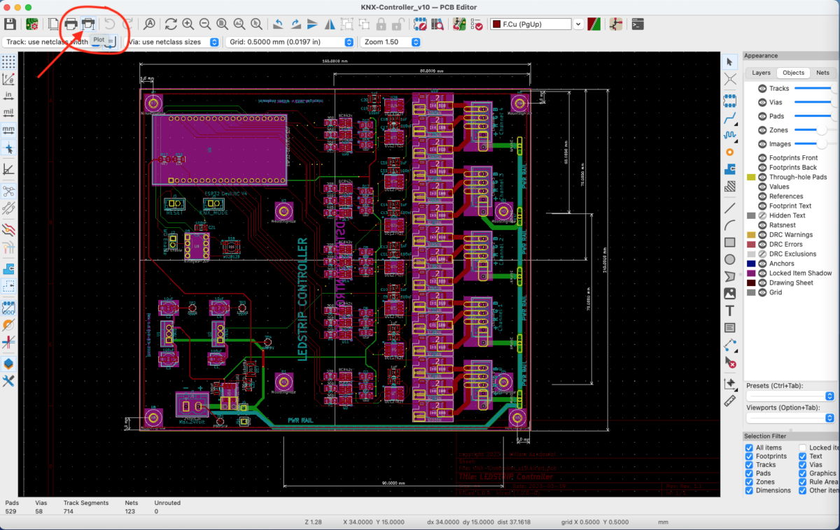
Therefore the design must be made suitable for the PCBWay production process. To do this you have to click on the [Plot] icon in KiCad’s PCB Editor
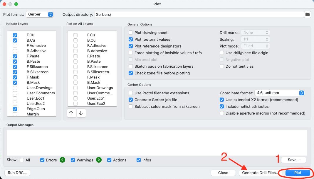
… and in the popup window that appears, click [Plot] and then [Generate Drill Files] …

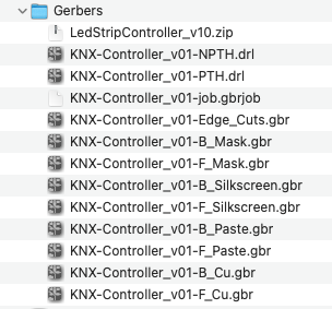
All files that have now been created (ending in “.gbr”, “.drl” and the file ending in “.gbrjob”) must be compressed into a single “.zip” file.
We will upload this “.zip” file to PCBWay later.
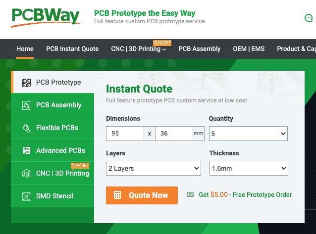
PCBWay has a nice website where you can easily order your printed circuit boards. To do this, go to “https://www.pcbway.com/”.
Start by entering the dimensions of your PCB design and click on [Quote Now] …
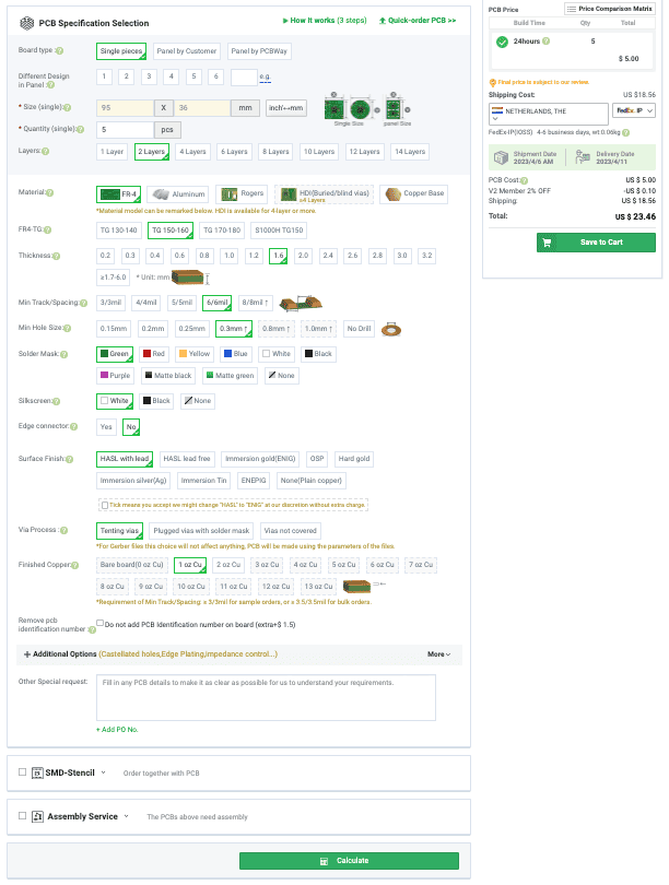
In the next screen you can provide additional information about how you want the printed circuit board to look. The most commonly used options are the colour of the Solder Mask (this sometimes involves extra costs or a longer production time) and the colour of the Silkscreen.
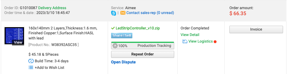
If everything is the way you want it, you will see a screen where you can upload the “.zip” file you just created in KiCad. The content is checked by people from PCBWay and if there are no problems, you will see the final costs and you can specify with which courier you want the printed circuit boards sent. There are major differences in price and delivery times. You may also have to deal with import duties/VAT. If you do not pay this in advance, the couriers charge a considerable fee for the handling. I therefore always choose “FedEx-IP (IOSS)“. You then pay an amount in advance (VAT Fee). After placing and paying for the order, you can follow the progress of production on the PCBWay site. PCBWay also sends a message when the printed circuit boards have been delivered to the courier.
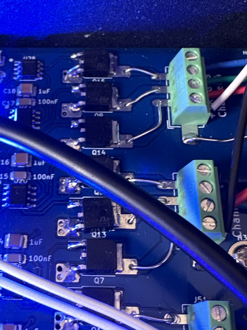
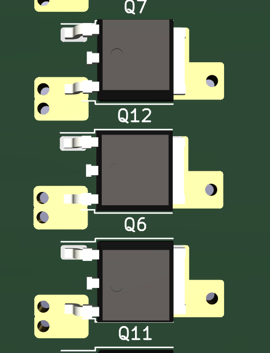
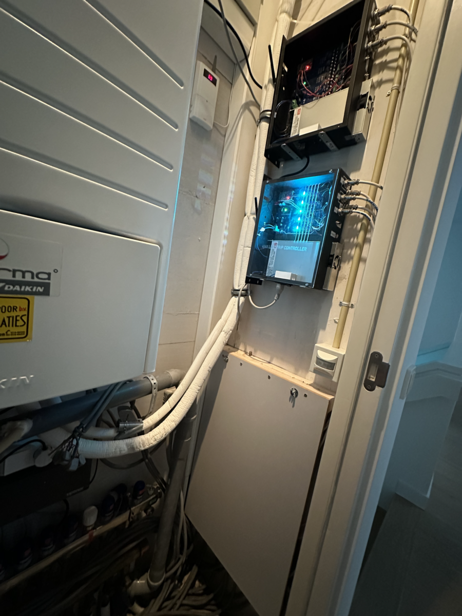
Gallery
 Follow