443 keer bekeken / views
In my post about the handheldAerosolSensor I use a circuit to switch power to the system with a single push-button, and then let the ESP32 turn it off again after completing measurements. This is an extremely efficient method because the alternative—putting the ESP32 into sleep mode—still consumes power and will eventually drain the battery, even in the “off” state.
This project is sponsored by
Using a single push-button to switch power on led me to design a separate circuit that allows that same button to both switch the power on and off, while the total current consumption in the “off” state is only a few microamps.
Een Nederlandse vertaling van de post kunt u hier vinden.
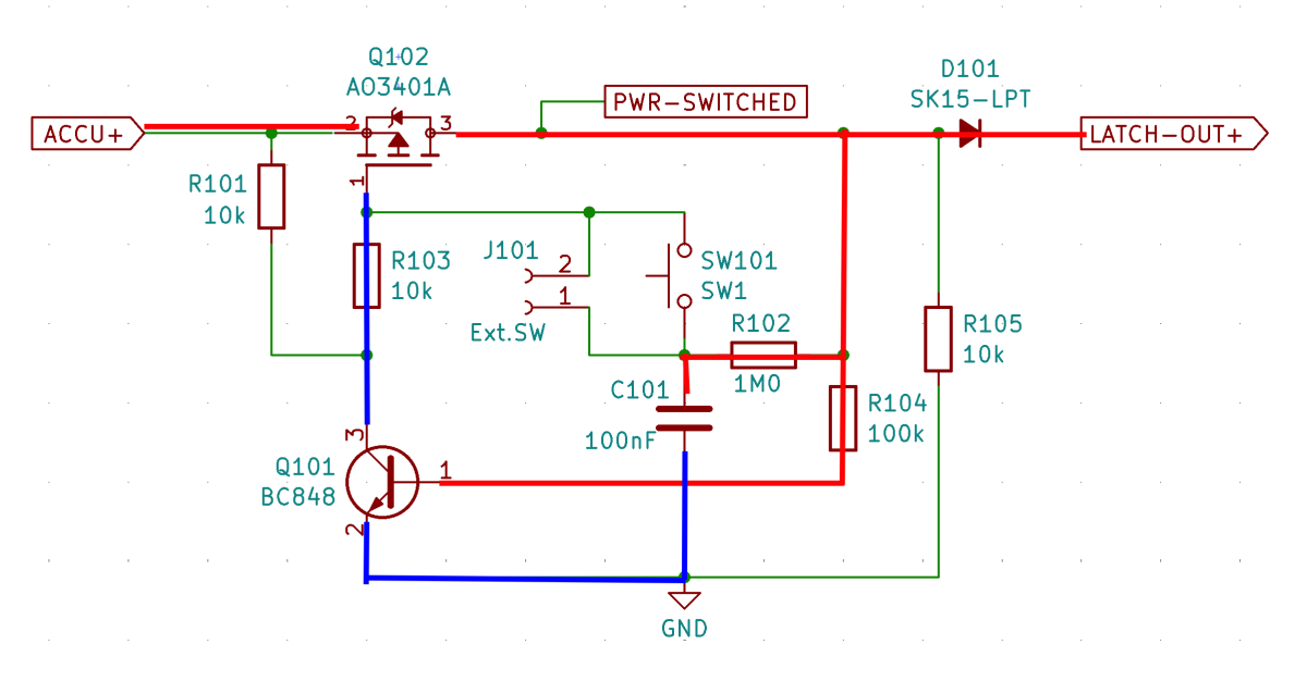
This is the complete schematic:
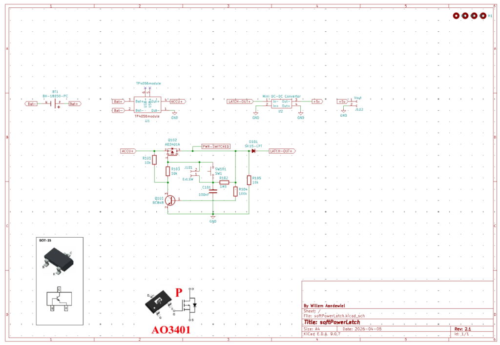
The schematic is quite simple and consists of only a few components. I chose the easy route and used a standard module for charging the Li-Ion battery (18650). I also used a standard step-up module to boost the battery voltage to 5 volts.
Operation of the Soft Power Latch Circuit
Initial state (off)
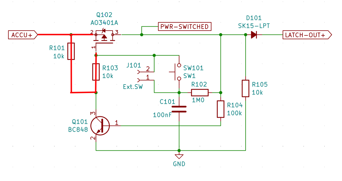
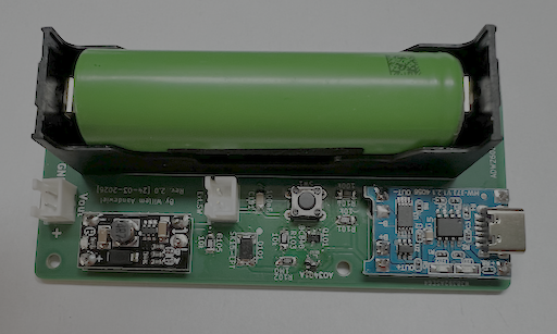
The battery is connected to the circuit (V+).
- C101 is empty (0 volts at the junction to SW1 and R102)
- Q101 has no base current and is “open”
- Q102 (MOSFET) is off (its gate is connected to V+ via R101 and R103)
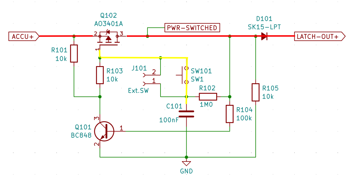
First press on SW1
- Because C101 is “empty”, the gate of Q102 is pulled to GND, causing Q102 to conduct
- The voltage at LATCH-OUT becomes (approximately) equal to V+
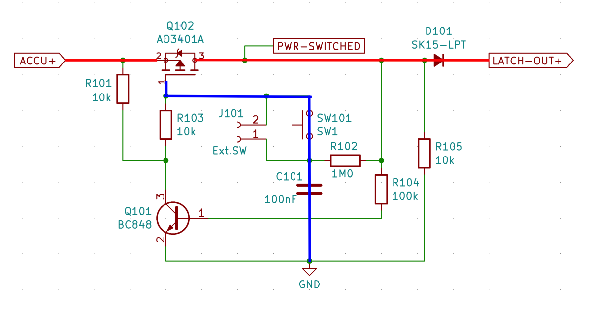
Latch formation
Now several things happen:
- Q101 receives base current via R104
- Q101 turns on (“closed”), pulling the collector to GND
- The collector of Q101 now pulls the gate of Q102 to GND
- Even if SW1 is released, Q101 will continue pulling the gate of Q102 to GND
- Meanwhile, C101 is charged via R102
This is the “latch effect”!
Second press on SW1
- C101 is now charged and will no longer pull the gate of Q102 to GND
- Pressing SW1 creates a short disturbance causing:
- Q101 to lose its base current and turn off (“open”)
- The gate of Q102 to be pulled up again via R101 and R103
- Q102 to turn off, causing the voltage at LATCH-OUT to disappear
The resistor R105 ensures that there is always “a small load”, which makes the circuit more reliable. The Schottky diode D101 is only needed if you want to switch a motor, because after switching off it keeps spinning for a while and acts like a dynamo, which interferes with the circuit. I have found that when connecting a step-up converter, such a diode is also really necessary!
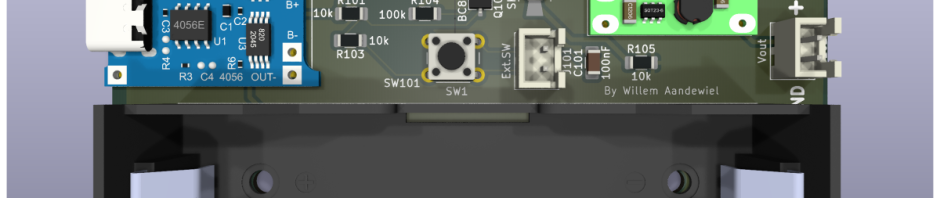
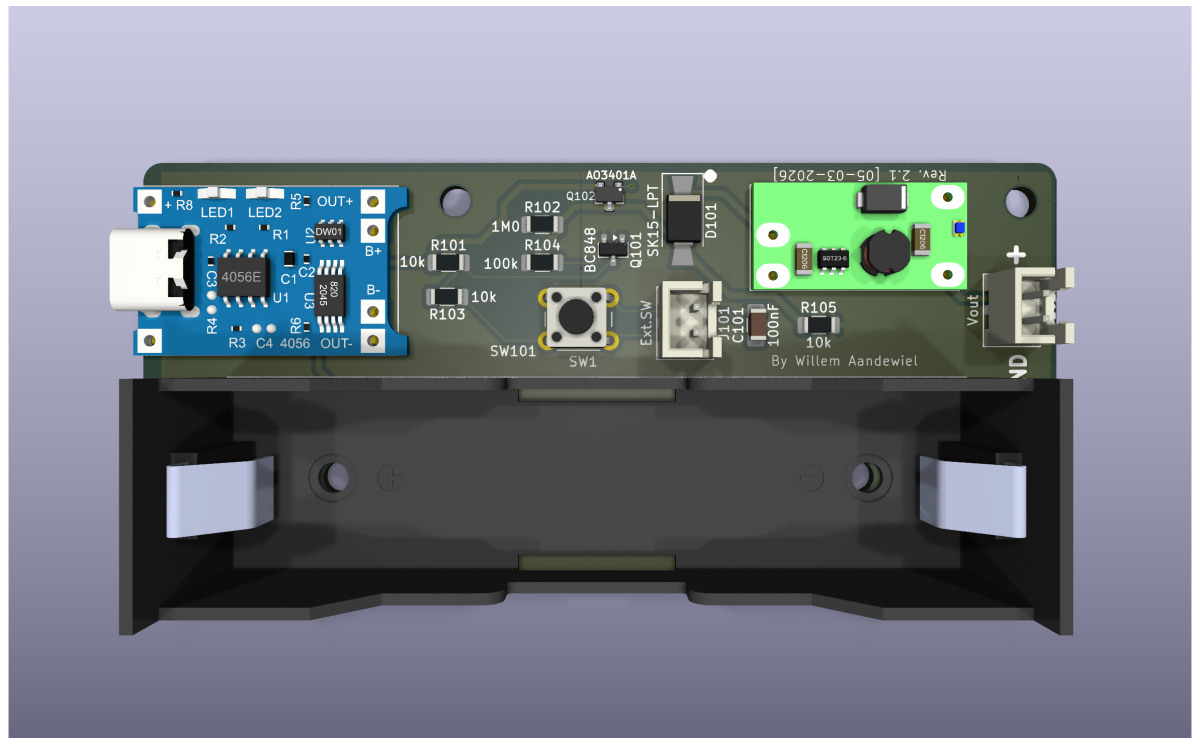
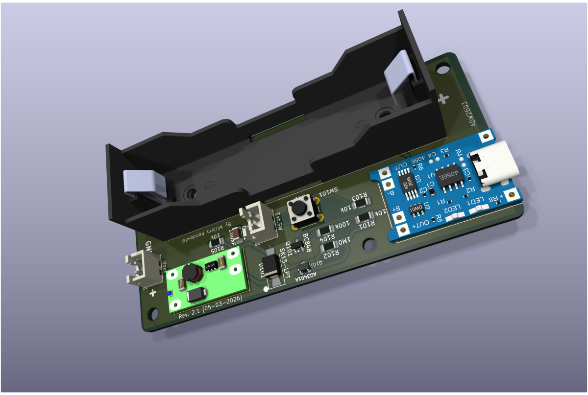
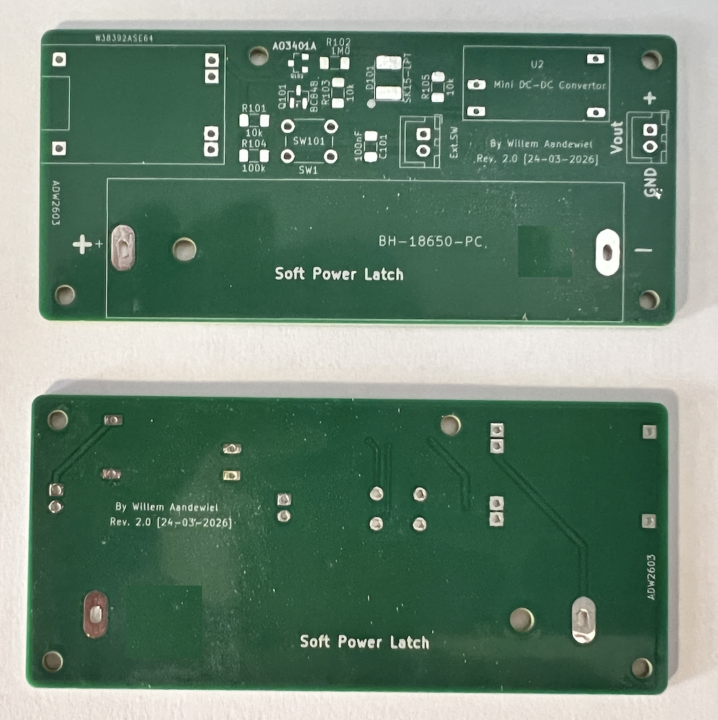
PCB Design
The PCB was designed using KiCad and then sent out to for manufacturing.
prides itself on delivering high-quality PCBs crafted with precision and attention to detail. Utilizing state-of-the-art manufacturing processes and cutting-edge equipment, PCBWay ensures that every board meets rigorous quality standards. Whether you’re prototyping a new project or mass-producing a commercial product, you can trust PCBWay to deliver PCBs that meet your exact specifications and performance requirements.
Parts list
- P-Channel MOSFET AO3401A (1x)
- NPN transistor BC848 (1x)
- Schotky Diode 1 Amp (1x)
- Resistors 10k (3x)
- Resistor 100k (1x)
- Resistor 1M (1x)
- Capacitor 100nF
- TP4056 Mini USB 5V 1A Lithium Li-Ion charge module from Amazon or AZ-Delivery but you can buy them all over the internet
- Mini DC-DC Boost Convertor Module 3,7 V tot 12 V from Amazon or AliExpress but also everywhere on the internet
- Push Button
- PCB from
If you want you can leave a reply.
 Follow