
The IR-receiver circuit
For receiving IR-codes an IR-receiver-diode is used. I chose the VS1838B which is a commonly used and available part that detects 950nm light at 38kHz.The VS1838B detects the 38kHz modulated IR-message and outputs a logic-pulse.
The VS1838B detects the 38kHz modulated IR-message and outputs a logic-pulse.
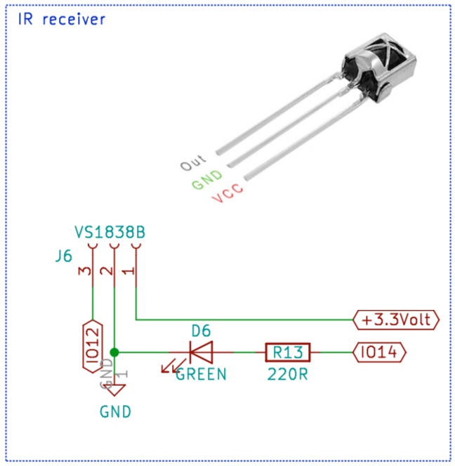
The IR receiver schematic
The output of the VS1838B is send to GPIO12 of the ESP8266 that will analyse and decode and eventually store the IR-message to a file.
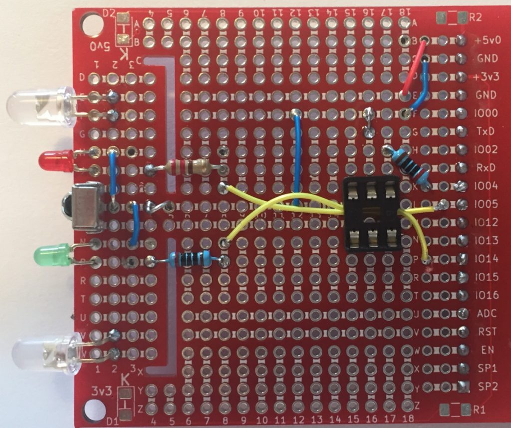
On the 1of!-Solderless board it looks like this. (mind you: The final design uses IO-14 for the green LED):
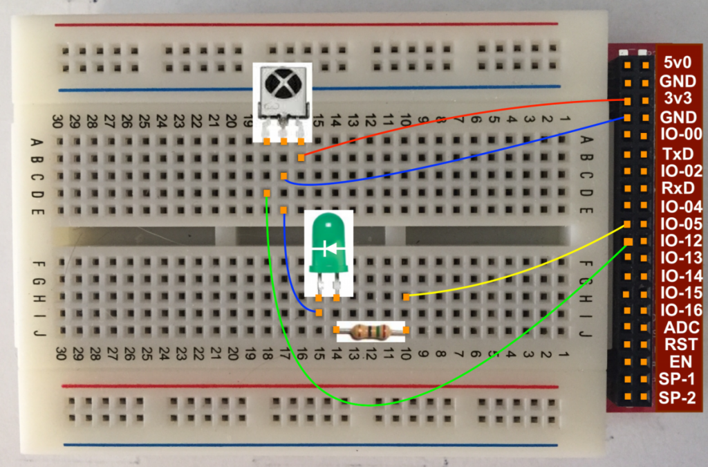
A green LED (D6) is connected to GPIO14 to give some visual indication the device is waiting for an IR-message to capture.
You can find a program (IR_receiver) to test this setup on github.
Compile and flash the IR-receiver sketch to the 1of!-Wemos (or 1of!-ESP12) board and open the Serial Monitor.
 IR_receiver is now running and waiting for IR input on Pin 12

 SPIFFS Mount successful

 Commands are:

   *D - remove file from SPIFFS
    L - List SPIFFS
    H - Help (this message)
    W - Write rawData to SPIFFS
    S - System Status
   *R - Reboot

 Timestamp : 000030.031
 Encoding  : NEC
 Code      : FFA857 (32 bits)
 Library   : v2.6.2

 Raw Timing[71]:
    +  9342, -  4392,    +   684, -   462,    +   658, -   488,
    +   716, -   430,    +   656, -   488,    +   598, -   546,
    +   684, -   460,    +   716, -   428,
    . . . .
    +   658, -  1624,    +   660, -   486,    +   714, -  1568,
    +   744, -  1516,    +   708, -  1594,    +   718, - 39748,
    +  9346, -  2124,    +   708

 uint16_t rawData[71] = {9342, 4392,  684, 462,  658, 488,  716,
 430,  656, 488,  598, 546,  684, 460,  716, 428,  716, 428,  714,
 1568,  686, 1596,  688, 1592,  658, 1624,  658, 1602,  738,
 1564,  664, 1618,
  . . .
 460,  658, 1624,  660, 486,  714, 1568,  744, 1516,  708, 1594,
 718, 39748,  9346, 2124,  708};  // NEC FFA857
 uint32_t address = 0x0;
 uint32_t command = 0x15;
 uint64_t data = 0xFFA857;

 [Enter: ‘w’]
 Write rawData to SPIFFS
 save pulses as: [Enter: ‘demo3’]
 save pulses as [/pls/demo3.pls] (y/N) [Enter: ‘y’]
 fileName is [/pls/demo3.pls]
 writeRawData(/pls/demo3.pls): number of pulses [71]
 9342, 4392, 684, 462, 658, 488, 716, 430, 656, 488, 598, 546,
 684, 460, 716, 428, 716, 428, 686, 460, 690, 1590, 688, 458, 688,
 456, 688, 438, 680, 484, 660, 1622, 684, 460, 658,
  . . .
 714, 1568, 744, 1516, 708, 1594, 718, 39748, 9346, 2124, 708,
 writeRawData(): saved [71] pulses

 [Enter ‘L’]
 /pls/pulse1.pls / 286
 /pls/demo1.pls / 306
 /pls/demo3.pls / 306
The IR-sender circuit
To be able to send IR-messages we need one or more IR LED’s. Using an IR LED is no different from using a “normal” LED, except for the fact that to get some reach the IR LED’s need far more current to do their job. Since the GPIO-pins of the ESP8266 are not capable of providing these high currents we need a driver circuit. Easiest is to use an opto-coupler like the 4N35 or 4N25 which doubles as a level-shifter from 3v3 (GPIO04) and 5 Volt to drive the Gate of the MOSFET switch.
The voltage drop over the IR LED is ~1.6Volt and the maximum current is 60mA. As we are using two IR LED’s in parallel and the duty cycle is 50%, the maximum current through R7 is 60*2*2=240mA. Therefor the value of R7 is (5-1.6)/240 => ~15 Ohm.
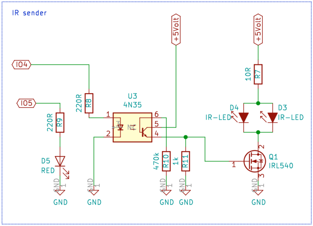
The pulses come from GPIO04. If GPIO04 is “high” the led in the optocoupler will ignite and, in turn, sets the transistor to conduct (Pulls the Emitter to 5 Volt). The 5 volt on the Emitter makes the Gate of Q1 “high” and the MOSFET now also conducts pulling the Drain to ground and so powering the two IR-LED’s (switching them “on”).
A “low” on GPIO04 switches the led in the optocoupler “off”. The transistor opens (no current flows from Collector to Emitter) and R11 pulls the Gate of Q1 to ground. The MOSFET now also does not conduct and no current will flow true the IR-LED’s (switching them “off”).
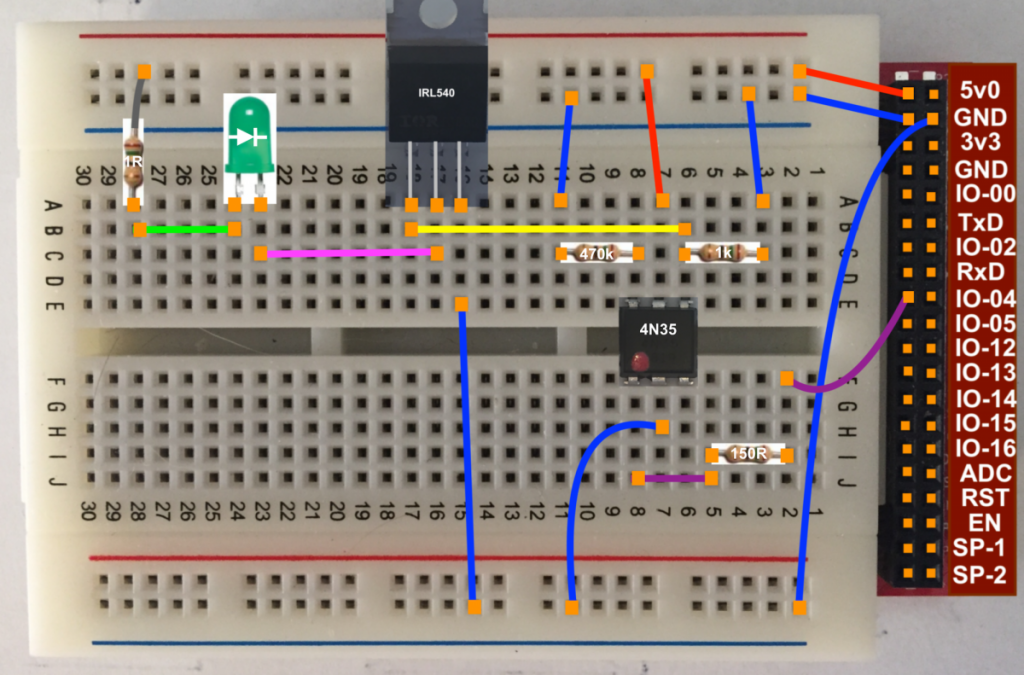
Mind you: in stead of an IR LED a normal LED is used for testing and therefor the 10 ohm resister (R7) must be 220 ohm!
You can find a program (IR_sender) to test this setup on github.
Compile and flash the IR-sender sketch to the 1of!-Wemos (or 1of!-ESP12) board and open the Serial Monitor.
 IR_sender is now running and sending IR on pin 4

 SPIFFS Mount successful

 Commands are:

   *D - remove file from SPIFFS
    L - List SPIFFS
    H - Help (this message)
    T - Transmit rawData from SPIFFS
   *R - Reboot

 [Enter: ‘L’]
 [01] [/pls/pulse5.pls]
 [02] [/pls/pulse1.pls]
 [03] [/pls/mutsiCool26.pls]
 [04] [/pls/demo1.pls]
 [05] [/pls/demo3.pls]

 [Enter: ‘t’]
 Transmit rawData from SPIFFS

 Pulse file number: [Enter: ‘3’]

 fileName is [/pls/mutsiCool26.pls]
 readRawData(/pls/mutsiCool26.pls):
 readRawData(): read [307] pulses


 Sending [307] pulses .. (redled blinks)
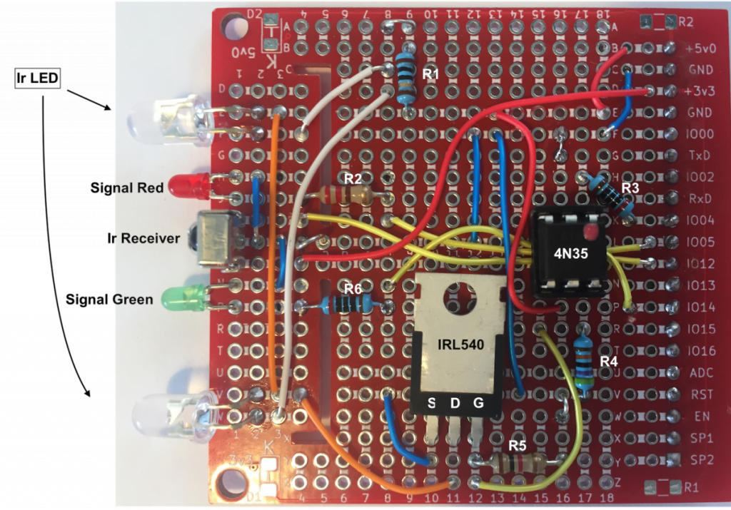
As the basics are working we can solder the IR-sender and IR-receiver circuitry’s to a 1of!-Proto board.
After confirming the signal-LED’s blink solder the rest of the circuit:
I must say, the range of the IR-sender circuit is not as good as I expected. Why is my TV-remote capable of switching channels by pointing it to the opposite wall and does my IR-sender needs to be pointed exactly to my TV? So I reversed engineered two of my remotes and was surprised that they use (almost) the same circuit to drive the IR-LED’s only they have both left out the serie resister (R7)!! As I do not want to blow my IR-LED’s I have reduced R7 to only 1 ohm and that enlarged the range quite a bit!
 Follow
Hoi Willem!
Leuk project, ik zocht nog zo iets! Ik wil mijn airco automatiseren op basis van sensoren van de omgeving (daarnaast ook de aansturing van een luchtbevochtiger en de automatische radiatorknoppen) om zo het klimaat op mijn kantoor optimaal te houden. Ik ga er zeker naar kijken!
Gr, Roland